4 - 6
4.4 Counting by Counter
Project name QB-4
Program name MAIN
K12
Set value in counter
C20
Y72
X1
C20
X7
0
5
7
RST
C20
*: OUT C is a 4-step instruction.
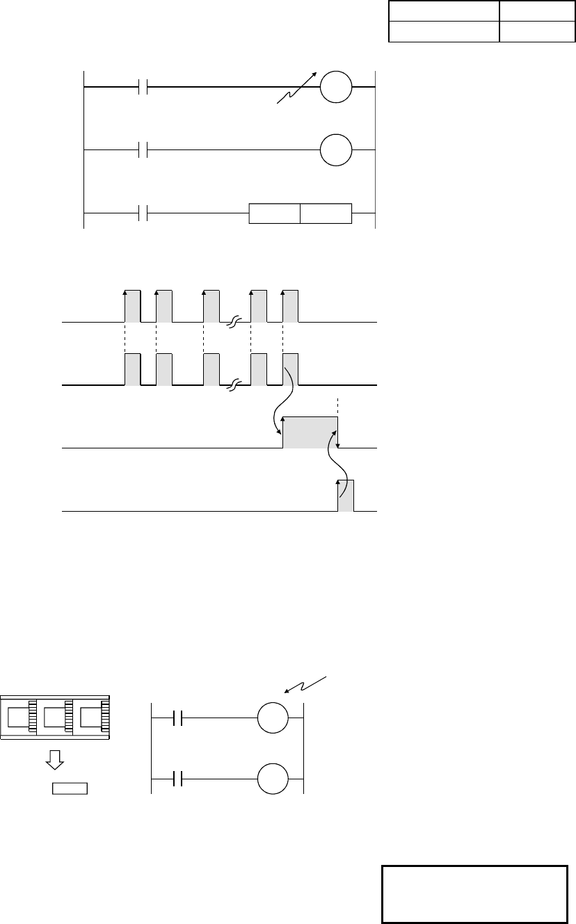
[Timing chart]
Contact X1
Coil C20
Contact C20, coil Y72
Contact X7 (input of RST instruction)
(Current value of counter)
12 3 1112 0
• The counter counts when
an input signal rises.
• After the count, the
subsequent input signals
are not counted.
• Once the counter counts,
the contact status and the
current counter value do
not change until the RST
instruction is executed.
• Executing the RST
instruction before the count
returns the counter to 0.
• The counter setting range
is from K0 and K32767. (K0
turns on (counts up) by the
execution of the
instruction.)
• In addition to the direct specification using K, indirect specification using D (data
register) is available.
• The counter C30 counts
when the number of rising
edges on the input signal
X0 becomes the same as
the number (such as 24)
specified by the data
register D10.
• This indirect specification is
useful for applying a value
specified with an external
digital switch to the counter.
024
D10 24
X0
C30
0
5
C30
Y71
D10
Set value
Digital switch
The indirect specification
using the data register D is
also available for the timer.


