1 - 12
(2) I/O numbers of a main base unit
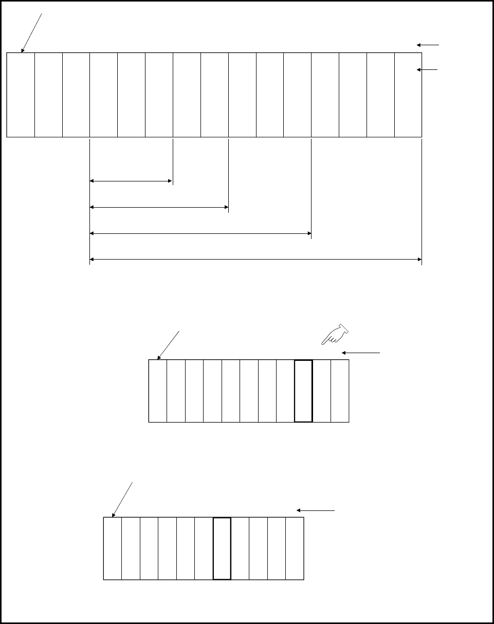
The I/O numbers of I/O modules which are attached to a main base unit are
assigned as follows. This configuration applies to both I/O modules and
intelligent function modules.
CPU
00 to 0F
10 to 1F
20 to 2F
30 to 3F
40 to 4F
50 to 5F
60 to 6F
70 to 7F
01
234567
Slot numbers
Main base unit(Q33B,Q35B,Q38D)B,Q312(D)B)
Base unit with
three slots(Q33B)
Base unit with five slots(Q35B)
Base unit with eight slots(Q38(D)B)
80 to 8F
90 to 9F
A0 to AF
B0 to BF
8 9 10 11
Base unit with 12 slots(Q312(D)B)
Power supply module
I/O numbers
• The I/O numbers of one slot (one module) are assigned in ascending order in 16-point unit (0 to F
H
).
As a standard, 16-point modules should be attached to all slots.
For example, the following figure shows the I/O numbers of when a 32-point module is attached to the fifth slot.
Power supply module
C
P
U
Main base unit
Slot numbers
0
1
2
3
4
5
6
7
The I/O numbers of the
slot next to the one with
32-point modules are
changed.
(The numbers are
assigned in order from
lower numbers.)
00 to 0F
10 to 1F
20 to 2F
30 to 3F
40 to 4F
70 to 7F
80 to 8F
50 to 5F / 60 to 6F
• The I/O numbers are also assigned to a vacant slot (a slot with no I/O module installed).
For example, if the third slot is vacant, the I/O numbers are assigned as shown below. (in the initial setting)
The number of assigned points can be changed by the setting.
Power supply module
CPU
Main base unit
Slot numbers
012
3
4
5
6
7
00 to 0F
10 to 1F
20 to 2F
40 to 4F
50 to 5F
60 to 6F
70 to 7F
Vacant slot
(30 to 3F)
• For the multiple CPU configuration (two to four CPUs), the I/O numbers are assigned from a slot next to a slot where
a CPU is attached.


