App. - 35
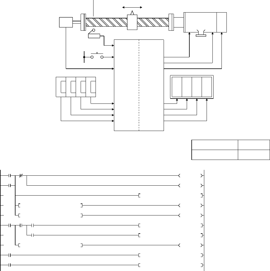
Appendix 4.22 Application example of positioning control
The following is an example of a positioning system with a pulse generator that
outputs pulses per motor, brake, and unit of distance.
In this system, a command value is set with the digital switch, and this set command
value is compared with the current value at start-up to determine in which direction,
forward or reverse, the motor rotates. The current value in the register D16 is
subtracted by 1 in forward direction, and incremented by 1 in reverse direction.
Positioning is completed when the command value matches the current value. The
current value is converted to a BCD value so that current position is represented in
4-digit decimal numbers.
X2
X0
X1
X20 to 23
X24 to 27
X28 to 2B
X2C to 2F
5 4 0 0
X1
X10
X100
X1000
X1000
X100
X10
X1
8263
mm mm
Command value setting switch Current value display
Y4C to 4F
Y48 to 4B
Y44 to 47
Y40 to 43
Y70
Y71
Y72
Start
MELSEC-Q
Pulse
generator
Home position
Forward
rotation
Reverse
rotation
Motor Brake
Home
position
Forward
rotation
Reverse
rotation
Brake
Project name QA-26
Program name MAIN
M0
0
X0 M2
M0
Y70
Y71
X2
During operation
Reads command value
Reverse rotation
Checks consistency with
command value
Displays current value
to exterior
D16D15<
D16D15>
M0 X1
D16D15=
SM400
D15K4X20BINP
Y72
Y71
Y70
D16K1-P
D16K1+P
M2
D16K0MOV
K4Y40D16BCD
Releases brake
Forward rotation
-1 during forward rotation
+1 during reverse rotation
Executes home position return
2
0
38
4
1
(always ON)


