


4 - 5
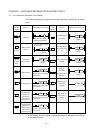
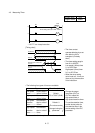
4.3 Measuring Timer
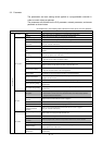
Project name QB-3
Program name MAIN
K30
Timer setting value (time limit: 3.0sec.)
T0
Y70
Y71
X5
T0
T0
0
5
7
*: OUT T is a 4-step instruction.
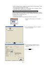
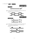
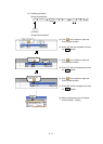
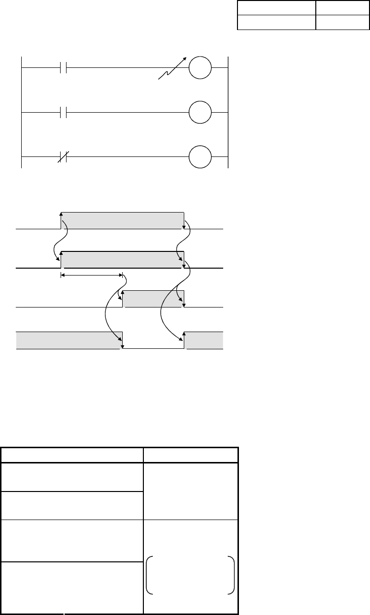
[Timing chart]
Contact X5
Coil T0
Normally open contact T0,
coil Y70
Normally closed contact 0b,
coil Y71
3.0sec.
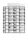
• The timer contact
operates delaying by a set
time after the coil is
energized. (On delay
timer)
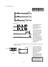
• The timer setting range is
from K1 to K32767.
Low-speed (100ms) timer
0.1 to 3276.7sec.
High-speed (10ms) timer
0.01 to 327.67sec.
• When the timer setting
value is set to 0, it turns on
(time-out) by the execution
of the instruction.
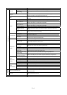
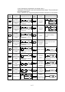
• The following four types of timer are available.
Type Timer No. (default)
Low-speed
timer·············
Counts time in
units of 100ms.
High-speed
timer·············
Counts time in
units of 10ms.
Default
T0 to T2047 (2048)
Low-speed
retentive
timer·············
Accumulates
time in units of
100ms.
High-speed
retentive
timer·············
Accumulates
time in units of
10ms.
Default: 0
The value can be
changed using the
parameter.
• Change the output
instruction (OUT) to
OUTH to select the
high-speed timer or
high-speed retentive timer.
• To use the retentive timer,
set the device points for
the retentive timer in the
device setting of the PLC
parameter.
Refer to section 6.4 for explanation on the retentive timers.