1 - 1
CHAPTER 1 BASICS OF PROGRAMMABLE CONTROLLER
1.1 Program
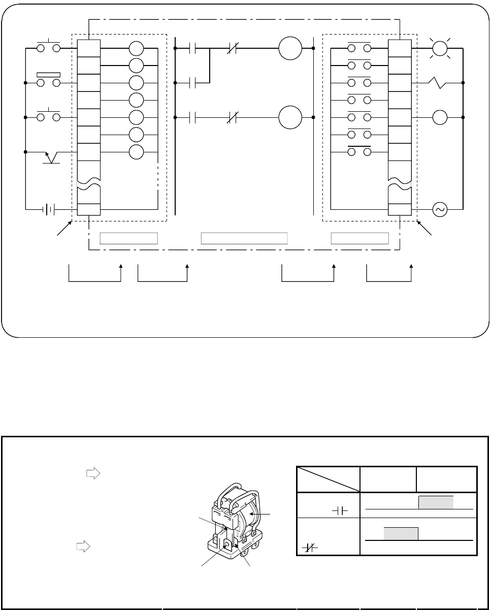
If a programmable controller is assumed as a control ladder, it can be described by
an input ladder, output ladder, and internal sequential operation.
PB
1
LS
1
PB
2
X0
X1
X2
X3
X4
X5
X6
Input relay
(virtual coil)
COM
Input module
Input circuit
Internal sequential operation
Output circuit
Y74
Output relay
K30
T1
Timer
T1
X6
X6
Y74
Y74
Y70
Y71
Y72
Y73
Y74
Y75
Y76
PL
Electromagnetic
valve
Magnet
contactor
Output module
Activates the
external loading.
Transmits the on/off
operations of the
output relay.
Activates the
internal sequential
operation by the
contact of the input relay.
Turns on/off the
input relay with
external signal.
COM
Contacts for
external
outputs
MC
(+) (-)
PLC
Sensor
Figure 1.1 Programmable controller configuration
A programmable controller is an electronic device centered around microcomputers.
Actually, a programmable controller is assemblies of relays, timers, and counters.
As shown in figure 1.1, the internal sequential operation is executed by turning on or
off the coil. The on/off condition of the coil depends on the connection condition (in
series or in parallel) and results of the normally open or normally closed contacts
"Relay", which is also called an electromagnetic relay, is a switch to relay signals. The relay is a key component to
make up a logic ladder.
Coil off
(always)
Coil on
(in operation)
Normally open
contact
Not conducted Conducted
Normally
closed contact
Not conductedConducted
1) Energizing the coil Magnetization
• The normally open contact closes.
(Conducted)
• The normally closed contact opens.
(Not conducted)
2) De-energizing the coil
Demagnetization
• The normally open contact opens.
(Not conducted)
• The normally closed contact closes.
(Conducted)
Normally
closed contact
Common
Normally
open contact
Coil


