


7 - 7
7.5 Q64AD Analog/Digital Converter Module
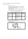
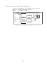
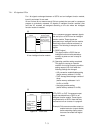
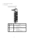
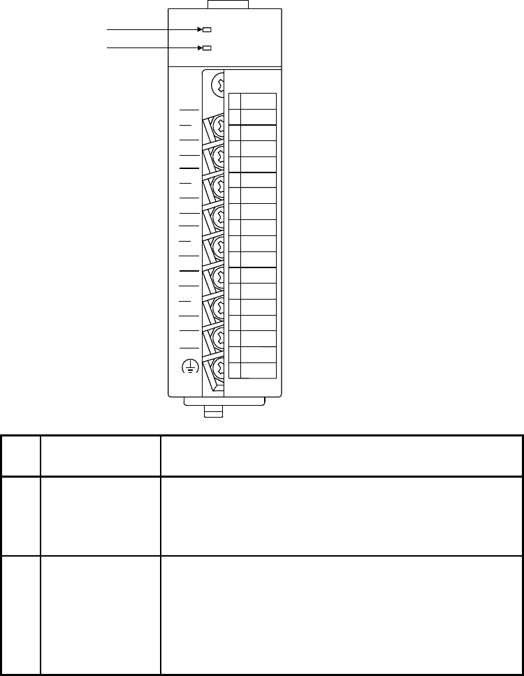
7.5.1 Names of parts
The following explains the parts of Q64AD.
For details, refer to the User's Manual.
Q64AD
Q64AD
RUN
ERROR
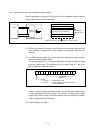
I+
V-
V+
SLD
(FG)
A/D
0-±10V
0-20mA
C
H
1
C
H
2
I+
V-
V+
SLD
I+
V-
V+
SLD
C
H
3
C
H
4
I+
V-
V+
SLD
A.G.
1
2
3
4
5
6
7
8
9
10
11
12
13
14
15
16
17
18
1)
2)
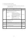
No.
Name and
appearance
Description
1) RUN LED
Indicates the operation status of the A/D converter module.
ON : In normal operation
Flicker : In offset/gain setting mode
OFF : 5V power failure or watchdog timer error occurred
2) ERROR LED
Indicates errors and the status of the A/D converter module.
ON : Error occurred
OFF : In normal operation
Flicker : Switch setting error occurred
Values other than 0 has been set to the switch 5
on the intelligent function module.