


5 - 49
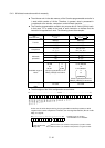
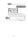
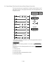
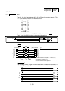
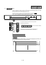
5.6 External Setting of Timer/Counter Set Value and External Display of Current Value
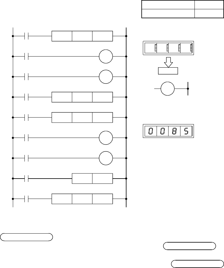
The timer and counter can be specified by K (decimal constant) directly or by D
(data register) indirectly. In the program shown below, the external digital switch can
change the set value.
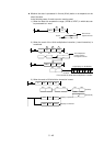
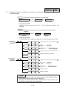
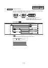
Project name QTC
Program name MAIN
X4
T10
D5
SM400
11
X1
D6
K4X30
15
BINP
X6
C10
RST26
4
X0
D5
K4X200BINP
T10
Y70
9
K4Y40T10BCD
X5
C10
D6
19
C10
Y71
24
SM400
K4Y50
C10
31
BCD
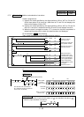
Digital switch
X2F to X20
1 2 3 4
D5 1 2 3 4
D5
T10
Digital display
Y4F to Y40
Displays the current
value of T10.
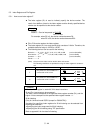
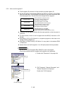
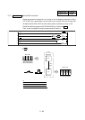
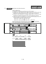
• After reading the program to GX Works2, write it to the programmable controller to
check that it works properly.
Operating Procedure
The step (1) of the following procedure is the same as
Operating Procedure
in
section 5.3.
The steps (2) to (4) of the following procedure are the same as
Operating Procedure
in section 4.4.
(1) Reading the data
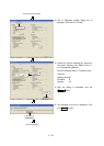
(2) Creating a program
(3) Writing the project to the programmable controller
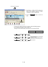
(4) Monitoring the ladder