App. - 50
1 1
1 1 1
0 0 0 0
0 0 1
1 1 1 1 1 1
0 0 1 0 0 1
0 0
0 0
0
0
1
1
0 0 0
0 00 0
1 1 1
1 1
0 0 0
0 00
0
0 0
1
0
1 0 0
00
0
1 0
1
F
16
F
1
F
48
F
33
F
32
F
17
F
64
F
49
F
50
16 16
7
23
D10
D10D0
Transferred by the MOVP instruction
Added by a
+P instruction
Number of ON inputs among X20 to 5B
D0
(2) Searching for ON devices shifting 32-bit data to right
DROR D0 K1
0
DMOV K8F1 D0
DMOV K8F33 D0
11 0 0 1
1 101 0 1
F
32
F
31
F
3
F
2
F
1
F
0
32 bits
D1,D0
D1
(16 bits)
D0
(16 bits)
DMOV instructio
n
DROR D0 K1
1 1 1 0 0 1 1 1 00 1 1 1 0 0 1
1 1 1 1 0 0 1 1 1 00 1 1 1 0 0 1
B31B30B29B28B27 B17B16B15B14B13 B0B1B2B3B4B5
D0D1
To B31
To B31
Carry flag
(SM700)
Contents of
B0 before
execution
Before
execution
After
execution
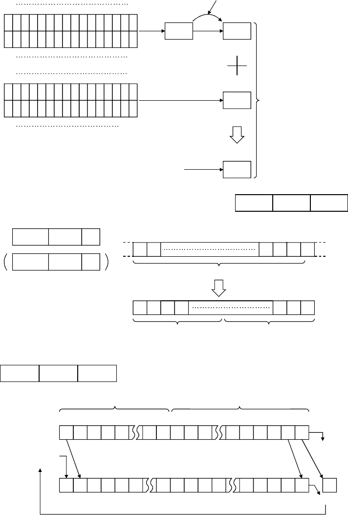
(a) Turning on X0 sets the above shift data (D0 and D1). After that, the data is
shifted right by 1 bit at each scan until a turned-on bit is detected.
When a turned-on bit is detected, shifting stops in that scan (SM700 turns
on), and the accumulated number of shifts (equivalent to a device number)
is displayed.
(b) Each time X1 is turned on, the next turned-on bit is detected and the
detected device number is displayed. At the same time, 1 is subtracted
from the number of turned-on bits which have been obtained in advance to
display the remaining number of turned-on bits.


