4 - 1
CHAPTER 4 SEQUENCE AND BASIC INSTRUCTIONS -PART 1-
4.1 List of Instruction Explained in this Chapter
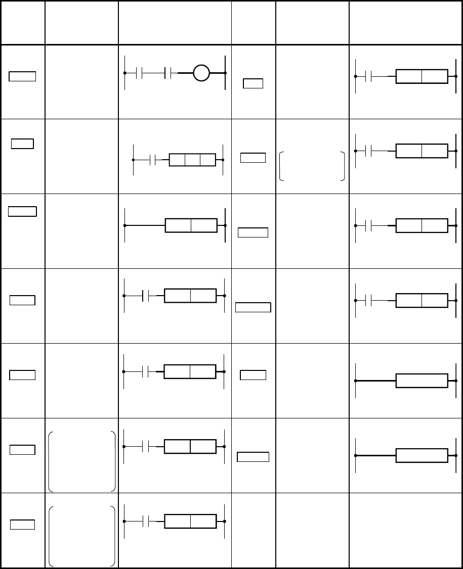
This chapter explains the sequence instructions and basic instructions as shown
below.
Instruction
symbol
(Name)
Function Drawing (devices to be used)
Instruction
symbol
(Name)
Function Drawing (devices to be used)
OUT
Out
Coil output
Specifies a bit of a bit
device or word device.
CJ
Conditional jump
(non-delay)
n = 0 to 4095
Pointer
CJ
Pn
MC
Master
control
Starting master
control
*1
n = 0 to 14
Nesting
Nn
Nn
MC
Specifies a bit of a bit device
or word device.
SCJ
Conditional jump
Jumps after one
scan
n = 0 to 4095
Pointer
SCJ
Pn
MCR
Master
control
reset
Terminating
master control
n = 0 to 14
Nesting
MCR Nn
CALL
Calling subroutine
program
n = 0 to 4095
Pointer
CALL
Pn
SET
Set
Setting devices
Specifies a bit of a bit device
or word device.
SET
CALLP
Calling a
subroutine
program (pulsing
operation)
n = 0 to 4095
Pointer
CALLP
Pn
RST
Reset
Resetting devices
Specifies a bit of a bit device
or word device.
RST
RET
Return
Returning from a
subroutine
program
RET
PLS
Pulse
Pulse
Generating the
pulses for one
program cycle
when a input
signal turns off
Specifies a bit of a bit device
or word device.
PLS
FEND
Terminating a
main routine
program
FEND
PLF
Pulf
Pulf
Generating the
pulses for one
program cycle
when a input
signal turns off
Specifies a bit of a bit device
or word device.
PLF
*1: In GX Works2, the on/off status of the master control is displayed in the title tag
on the monitor screen.


