4 - 37
Hint
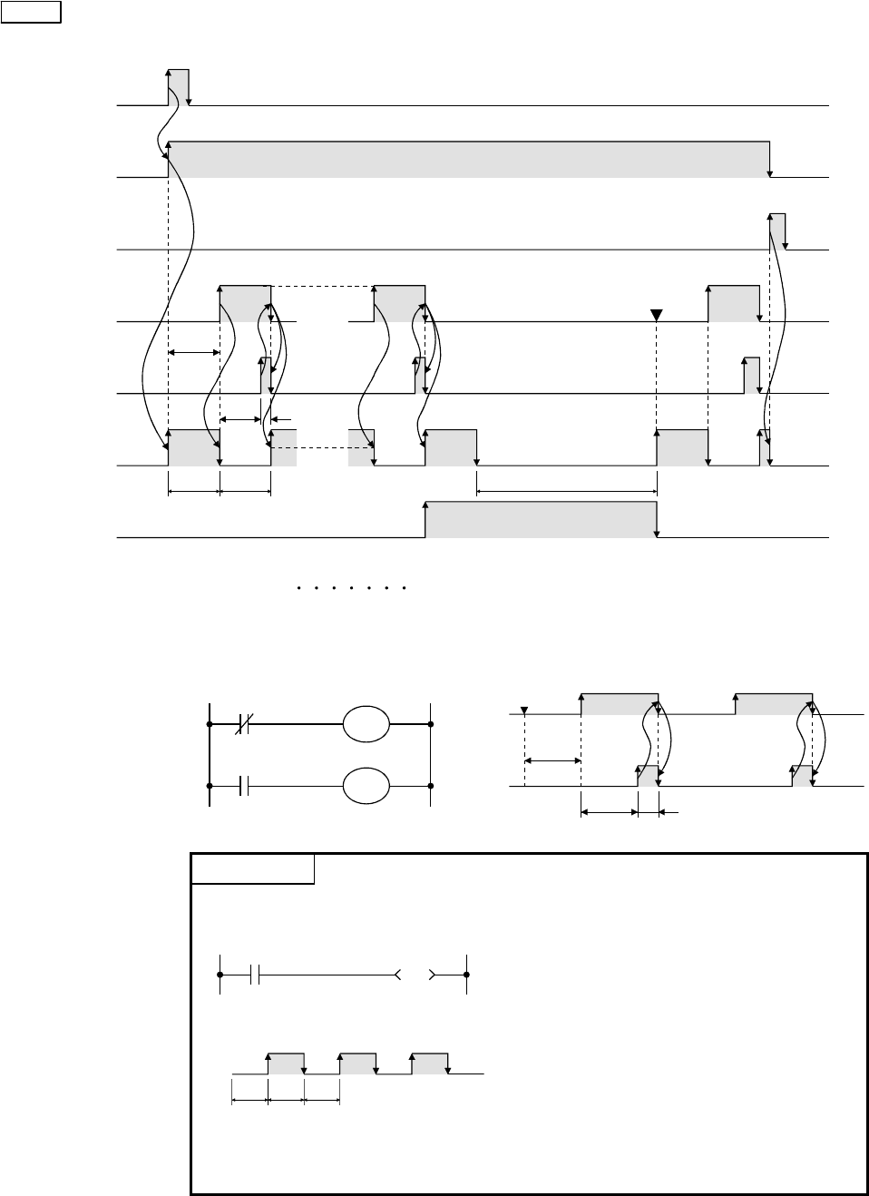
(1) The following shows the timing chart of the program.
X0
M0
X1
Contact T0
Contact T1
Y70
Contact C0
1sec.
1sec. 1sec.
1sec
One scan
5sec.
Restart
Counter of C0
1. 2. 10. 1. 2.0.
(2) The following shows the basic flickering ladder and its timing chart.
[Ladder] [Timing chart]
T1
T0
T0
T1
K10
K10
Contact
T0
Contact
T1
1sec.
1sec.
One scan
Start
REFERENCE
• The flickering ladder can be created using the special relay that generates
clock as shown below.
SM413 (2-sec. clock)
Y70
[Timing chart]
Y70
1sec.1sec.
1sec.
In addition to the SM413 (2-sec. clock) on
the left, the following can be used.
SM409 (0.01-sec. clock)
SM410 (0.1-sec. clock)
SM411 (0.2-sec. clock)
SM412 (1-sec. clock)
SM414 (2n-sec. clock)
SM415 (2n-msec. clock)
The clock starts from OFF when the
programmable controller is reset or the
power is turned on.


