App. - 3
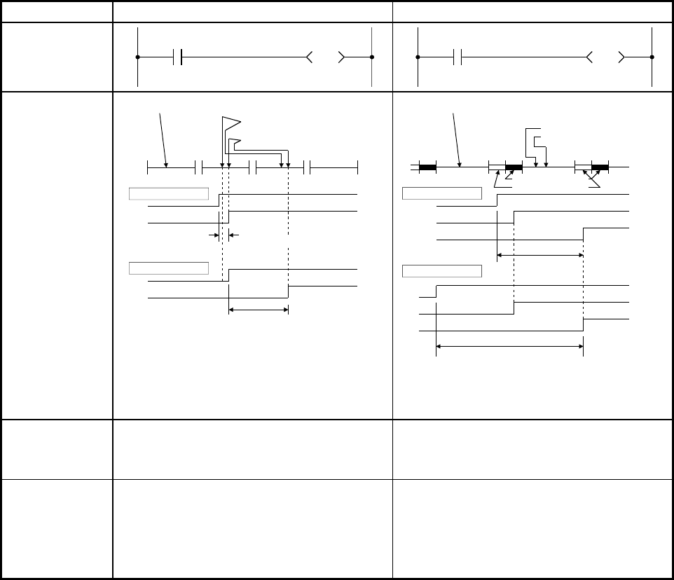
Appendix 1.3 Comparisons between the direct mode and refresh mode
In the example ladder given below, turning on input X0 turns on output Y70.
Item Direct mode Refresh mode
1. Ladder example
Y70
DX0
Y70
X0
END
Internal input
Input instruction (LD X0)
Output instruction (OUT Y70)
Program execution
0
Minimum delay
Maximum delay
X0
X0
Y70
Y70
0
END
0
Delay
(One scan)
Delay
(Two scans)
Input refresh
Output refresh
Internal input
2. Response lag
from when input
is changed to
when output is
changed
accordingly
END END
Delay
(
One scan
)
Delay
(execution time of the instruction)
Input instruction (LD X0)
Output instruction (OUT Y70)
Program execution
0000
Minimum delay
Maximum delay
X0
Y70
X0
Y70
• The delay time ranges from 0 (only execution
time of the instruction) to 1 scan.
• The delay time is 0 to 1 scan.
• The delay time ranges from 1 to 2 scans.
• The delay time is 1 to 2 scans.
3. Execution time
of the I/O
instruction
• The direct mode needs longer time than the
refresh mode since a programmable controller
accesses I/O modules.
• Generally, only short time is needed since a
programmable controller accesses data
memory.
4. Scan time
• The scan time is longer for the execution time
of the I/O instructions.
• The actual scan time is the program execution
time.
• The scan time is shorter for the execution time
of the I/O instructions.
• The actual scan time is the total time of a
program execution, input transfer, and output
transfer.


