3 - 1
CHAPTER 3 DEVICE AND PARAMETER OF PROGRAMMABLE CONTROLLER
3.1 Device
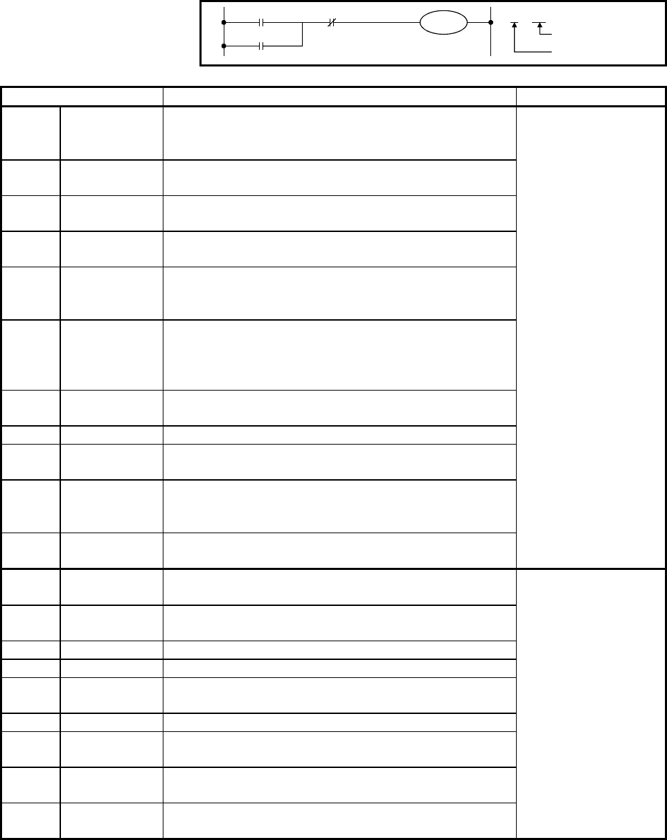
A device is an imaginary element for programming in the programmable controller
CPU, as well as the components (such as contacts and coils) that compose a
program.
X6
Y74
T2
Y74
Y
Device No.
Device symbol
74
Type Description Remark
X Input
Sends commands and data to a programmable controller
through external devices such as push buttons, selector
switches, limit switches, and digital switches.
Y Output
Outputs control results to solenoids, electromagnetic switches,
signal lights, and digital indicators.
M Internal relay
Auxiliary relay inside a programmable controller that cannot
output directly to external devices
L Latch relay
Uninterruptible auxiliary relay inside the programmable
controller that cannot output directly to external devices
B Link relay
Internal relay for data link that cannot output directly to external
devices The area not assigned by initial link information setting
can be used as an internal relay.
F Annunciator
Used for failure detection. Create a failure detection program
beforehand and turn on the program while the programmable
controller is running to store numerical values in the special
register D.
V Edge relay
Internal relay that stores an operation result (on/off information)
from the top of a circuit block
SM Special relay Internal relay that stores CPU statuses
SB Special link relay
Internal relay for data link that indicates a communication
status and errors
FX Function input
Internal relay that captures the on/off data specified by a
subroutine call instructions with arguments in a subroutine
program
FY Function output
Internal relay that passes an operation result (on/off data) in a
subroutine program to a subroutine program call source
• Bit device
• Mainly handles on/off
signals.
T(ST) Timer
Accumulative timers of four types: low-speed timer, high-speed
timer, low-speed integrator, and high-speed integrator
C Counter
Accumulative counters of two types: counters for sequence
programs and counters for interruption sequence programs
D Data register Memory that stores data in the programmable controller
W Link register Data register for data link
R File register
Register for an extensive use of data registers, which uses the
standard RAM or memory card
SD Special register Register that stores CPU statuses
SW Link data register
Data register for data link that stores a communication status
and failure information
FD Function register
Register for the exchange data between a subroutine call
source and a subroutine program
Z Index register
Register for modification to the devices (X, Y, M, L, B, F, T, C,
D, W, R, K, H, and P)
• Word device
• Mainly handles data.
• One word consists of
16 bits.
• Can be specified by
entering ~.* (* = 0 to F
(hexadecimal)).


