1 - 13
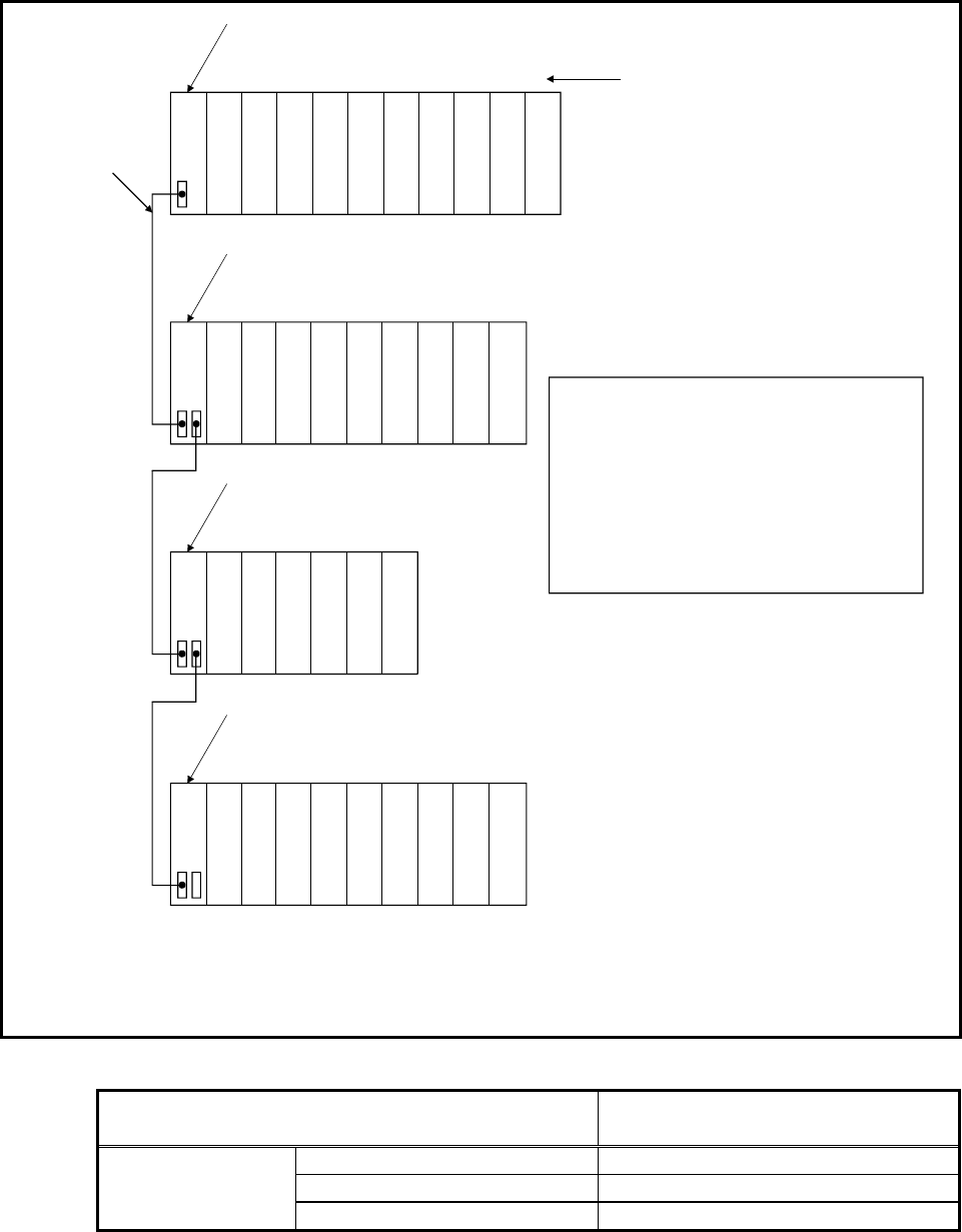
(3) I/O numbers of an extension base unit
Connect an extension base unit when the number of slots of the main base unit
is insufficient.
The I/O numbers are assigned as follows in the initial setting.
This configuration applies to both I/O modules and intelligent function modules.
Power supply module
CPU
Slot numbers
012
3
4
5
6
7
Extension base unit (Q68B)
8
9
10
11
12
13
14
15
(Q65B)
16 17 18
19
20
Extension base unit (Q68B)
21 22 23
24
25
26
27
28
Extension cable
First extension
base unit
Second
extension base
unit
Third extension
base unit
(Note)
Parameters allow the setting different from the
actual number of slots.
For example, a base unit for 12 slots can be set as
a base unit for 3 slots and vice versa.
This is in order to handle the future extension, and
to prevent the gap of I/O numbers which is likely to
happen when a conventional system is shifted to the
new one.
For details, refer to the QnUCPU User's Manual
(Function Explanation, Program Fundamentals).
Main base unit (Q38(D)B)
Power supply modulePower supply modulePower supply module
00 to 0F
10 to 1F
20 to 2F
30 to 3F
40 to 4F
50 to 5F
60 to 6F
70 to 7F
A0 to AF
80 to 8F
90 to 9F
B0 to BF
C0 to CF
D0 to DF
E0 to EF
F0 to FF
100 to 10F
110 to 11F
120 to 12F
150 to 15F
1C0 to 1CF
130 to 13F
140 to 14F
160 to 16F
170 to 17F
180 to 18F
190 to 19F
1A0 to 1AF
1B0 to 1BF
• The slots of the extension base unit are also assigned in ascending order in 16-point unit.
• The start I/O number of the extension base unit is assigned from the last number of the main base unit or of the
previous extension base unit.
• Setting "0" to the parameter can assign the I/O number to the vacant slot or areas with no slot.
The following table shows the number of available extension base units.
CPU type Number of stages (including the ones
connected with GOT in bus connection)
Q00UJCPU 2
Q00UCPU, Q01UCPU, Q02UCPU 4
Universal model
Other than the above 7


