App. - 24
Appendix 4.16 Measuring operation time
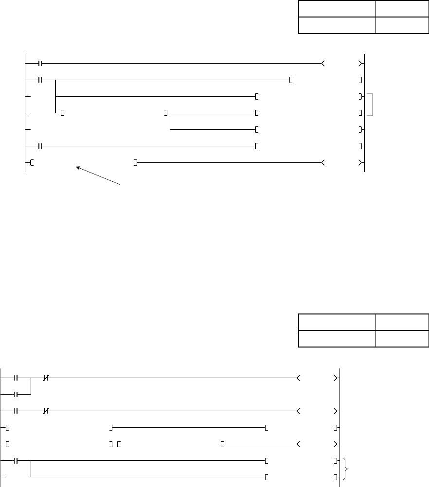
Setting an operation time to a control target is useful for judging the timing of a
component replacement and lubrication. The timer ST and data register D must
have a backup power source so that they can continue operating at a power failure.
With the contents of D31 (in one hour units) displayed externally, the program can
work as an operation timer.
Project name QA-23
Program name MAIN
ST250
X2
ST250
0
5
Measures in
1 hour units
6-minute timer
Indicates timing
to replace
K3600
D30K0MOV
ST250RST
D30K1+
D31K1+
K4Y60D31BCD
D30K10=
SM400 (always ON)
21
D31K1000<=
25
Y70
1-hour timer
Outputs operation
time to exterior
The management time is set to 100 hours.
Appendix 4.17 Measuring cycle time
Measuring the operation time of a control target (from its start to end) allows
displaying the cycle time-out and managing a control time lag.
The following ladder in which the <, >, and = instructions are used to determine the
state of T200 indicates a cycle time-out and measures a time lag with the counter.
Project name
QA-24
Program name MAIN
M56
X0
M56
0
4
Measures cycle time
In cycle
X1
M56
T200
X7
24
T200
K32760
Y70SET
10
T200K400<
14
T200K300< T200K400>= C10
K32760
Y70RST
C10RST
Cycle time run out
Number of cycle times
of 3.01 to 4.00sec.
Clears time out display
and accumulated counts


