


7 - 3
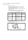
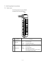
7.2.1 I/O signals to CPUs
For 1-bit signals exchanged between a QCPU and an intelligent function module,
input Xs and output Ys are used.
Xs and Ys here do not mean external I/Os but symbols that are used in a sequence
program to exclusively represent I/O signals of intelligent function modules. Also
note that I/O numbers are assigned according to the slot where the intelligent
function module is installed.
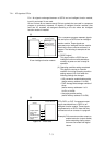
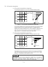
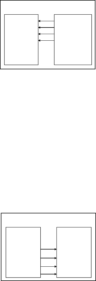
[X]
QCPU
Intelligent
function module
X
X
X
X
READY signal
Operating condition
setting completed
Error
A/D conversion completed
Figure 7.3
X from intelligent function module
Xs in a sequence program represent signals
that are input to a QCPU from an intelligent
function module. These signals are
generated on an intelligent function module.
Note that the Xs are used as contacts in a
program. The following is examples of the
signals.
(1) READY signal
This signal notifies a QCPU that an
intelligent function module started up
normally at power-on and is ready for
operation.
(2) Operating condition setting completed
This signal is used as an interlock
condition for turning Operating condition
setting request (Y9) on/off when the
following settings are changed.
• A/D conversion enable/disable setting
(buffer memory address 0: Un\G0)
• CH Average time/average number of
times
(buffer memory addresses 1 to 8:
Un\G1 to Un\G8)
• Averaging process setting
(buffer memory address 9: Un\G0)
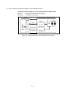
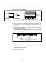
[Y]
QCPU
Intelligent
function module
Output enable
Y
Y
Y
Y
Channel change
Synchronous
output
User range
writing
Figure 7.4 Y from CPU
SETs, RSTs, or OUT-Ys represent output
signals transmitted from a QCPU to an
intelligent function module. These signals
are generated on a QCPU. Note that they
are used as coils or contacts in a program.
(Example) D/A converter modules output an
enable instruction (output enable)
before outputting analog values
that were converted from digital
values.