


11-7
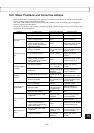
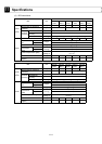
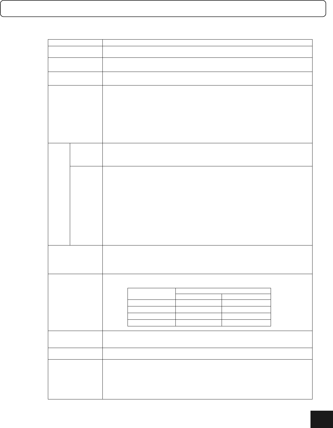
(6) Driver Function Specifications
Item Specifications
Higher interface
RS232C interface (single channel communication, multi-channel communication)
Controller interface (pulse train position command)
Mechanical input
signal
Homing signal, (+) direction hardware over-travel signal, (-) direction hardware over-travel
signal, emergency stop input signal
Mechanical input
signal
Brake signal (can be switched between clamp and dynamic brake applications with a
parameter)
Encoder resolution
(position command
resolution when
shipped)
Rotating type DM1000A series ; 4096000 pls/rev (1024000 pls/rev)
DM1000B series ; 2621000 pls/rev (655360 pls/rev)
DM1004B/C ; 2621000 pls/rev (655360 pls/rev)
DR1000A series ; 1638400 pls/rev (819200 pls/rev)
DR1000B series ; 1015808 pls/rev (507904 pls/rev)
DM1000E series ; 1228800 pls/rev (614400 pls/rev)
DR5000B series ; 557056 plc/rev (278528 pls/rev)
DR5000E series ; 638976 pls/rev (319488 pls/rev) stiffness series: 0.5 µm,
Linear LM1/2 ; 0.25 µm (0.25 µm)
LM3/5 ; 0.5 µm (1.0 µm)
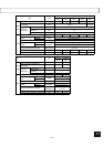
Method
I-PD position control (position: integral proportional control, velocity: proportional control)
Various feed forward functions (position, velocity, acceleration)
Various standard filters (velocity command filter, velocity feedback filter, first order delay filter)
Optional filter (notch filter 2 channels)
Control
part
Adjustment
Position control bandwidth:1 Hz to 32Hz, velocity control loop width: 5Hz to 200Hz
Position integral limiter setting
Various feed forward percentages (position, velocity, acceleration)
Various standard filter settings (velocity command filter bandwidth, velocity feedback filter
enable/disable, bandwidth, first order delay filter setting)
Optional filter setting (notch filter bandwidth)
*1) Calculates proportional gain and acceleration feed forward gain of the velocity control part
automatically based on measurement by the auto-tuning operation or manual setting of
the load inertia/weight with respect to the settings of velocity control bandwidth and
acceleration feed forward percentage.
*2) Calculates position control bandwidth, velocity control loop bandwidth, and position
integral limiting value automatically during execution of the auto-tuning operation or by
manual setting of the servo stiffness
Acceleration/decelerat
ion control
Trapezoidal move: Acceleration curve and deceleration curve can be selected individually.
Acceleration time or deceleration time can be selected individually (with respect to the
maximum velocity).
*3) Real time override possible, interlock possible
Operation function
Follows the position command from the controller interface when none of the operations listed
below is being performed.
Protection functions
Encoder/resolver error, power module error (over-voltage and over current), main power
supply error, overload, maximum velocity, excessive position deviation, hardware over-travel,
software over-travel (only for linear coordinate)
Others
Support software PC utility running under Windows (optional)
Possible to connect the operation display pendant (optional)
Monitor
Analogue signal monitor (velocity, general, torque/thrust command)
For general monitoring, what is shown by the monitor can be selected by setting (position error,
test operation response, position command value, current position value, position command
differential value)
Digital signal monitor (settling signal)
Monitoring internal information by higher interface
Error and alarm display on a 7-segment LED
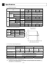
Pulse train
Operation
Controller interface RS232C interface
Homing operation
○○
Test operation
○○
Auto-tuning
○○
Jog move
×○
11