


-i-
Table of Contents
Introduction..........................................................................................................................1
Chapter 1 Overview of the Product 1-1
1.1 About the DYNASERV DM/DR Series ................................................................... 1-2
1.2 About the DrvGII Type Driver ................................................................................. 1-3
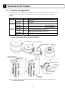
1.3 Product Configuration .............................................................................................. 1-4
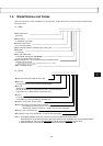
1.4 Model Names and Codes .......................................................................................... 1-5
1.5 Name and Function of Each Part .............................................................................. 1-6
1.6 System Configuration Diagram .............................................................................. 1-10
Chapter 2 Installation 2-1
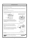
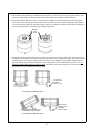
2.1 Installation of the Motor ........................................................................................... 2-2
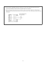
2.2 Installation of the Driver........................................................................................... 2-3
Chapter 3 Connection and Wiring 3-1
3.1 Diagram of Overall Connection................................................................................ 3-2
3.2 Cable Specification List............................................................................................ 3-3
3.3 Connection between Motor and Driver .................................................................... 3-4
3.4 Wiring of Motor, AC Power Supply, and Ground Cable.......................................... 3-6
3.5 Wiring of Encoder Cable .......................................................................................... 3-8
3.6 Wiring of Controller Cable ....................................................................................... 3-9
3.7 Wiring of Sensor Brake Terminal ........................................................................... 3-10
3.8 Wiring of Regenerative Alarm Contact <CNA>
(For 500W Level Drive Only) ................................................................................ 3-11
Chapter 4 Basic Settings for Operating the Motor 4-1
4.1 Procedure (Flowchart) .............................................................................................. 4-2
4.2 Preoperation check.................................................................................................... 4-3
4.3 Installing the PC Utility on the PC ........................................................................... 4-6
4.3.1 Procedure .......................................................................................................................................4-6
4.3.2 Startup............................................................................................................................................4-8
4.4 Preparation................................................................................................................ 4-9
4.4.1 Selecting Communication Port ......................................................................................................4-9
4.4.2 Selecting Channels.........................................................................................................................4-9
4.4.3 Displaying Communication Strings .............................................................................................4-10
4.4.4 Main Menu...................................................................................................................................4-11
4.5 Setting the Status to Servo ON ............................................................................... 4-12
4.6 Auto-tuning............................................................................................................. 4-14
4.7 Performing Homing Operation ............................................................................... 4-16