


5-10
Functions
5
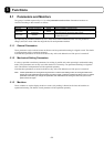
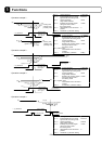
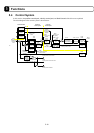
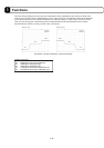
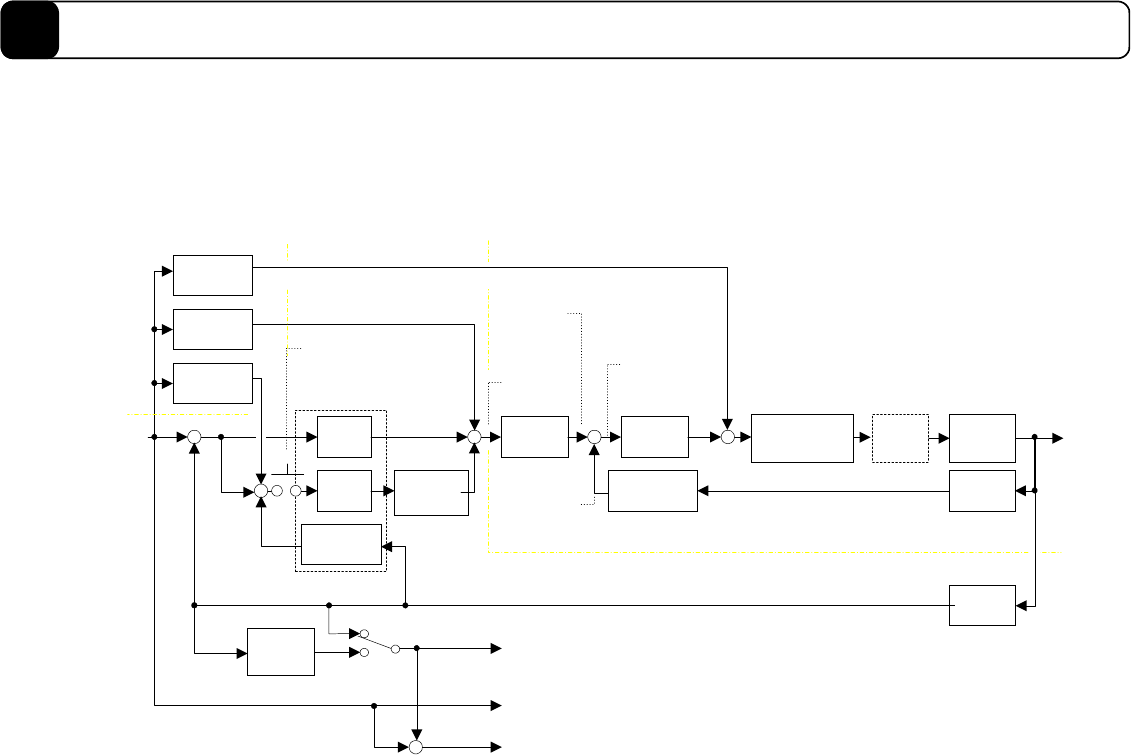
5.4 Control System
In this section, the position control part, velocity control part, and feed forward of the driver are explained.
The block diagram of the control system is shown below.
Proportio
nal
control
Integral
control
Position
integral
limiting value
Differential
feedback
Velocity feed
forward
Acceleration
feed forward
+
Integral main
switch
Velocity
command
filter
Velocity
feedback filter
Velocity
proportional
gain
First order delay
compensation
device setting
Notch
filter 2Ch
Motor
mechanical
system
#387
Motor linear
coordinate
command
value
Motor
position
Velocity
sensor
Position
sensor
+
+
+
+
-
+
-
+
-
+
+
Position
current
value filter
Motor linear coordinate
current value after filtering
Motor linear coordinate
current position
Velocity value
(digital)
Velocity
command value
after filtering
(digital)
Velocity current
value
after filtering
Velocity current value
Pulse position current value
#50
#48
#53
#59
#221
#361←#51
#49
#219,#220
#152
#153,#154
#155
#360
#356
#355
#388
#321
#384
#366
#365
#363
#364
Velocity error
(digital)
#365
Velocity
control part
Position
control part
Feed forward
-
+
Position feed
forward
Motor linear
coordinate
deviation
#389
#203
Pulse position command value
#320
Pulse position deviation
#322
←
#54
#55
#56