


6-3
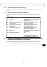
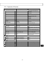
6.1.2 Explanation of Terminals
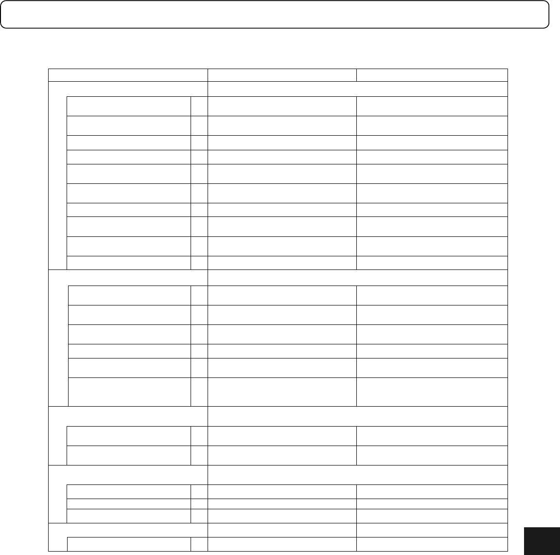
Signal name Description
Contact input signals Total 12 points
IN_MODE_START 1 Operation start command
Starts operation when setting from
OFF to ON.
IN_ABORT 1 Operation abort command
Stops operation when setting from
OFF to ON.
IN_MODE1, 0 2 Operation mode number
IN_PLS_DIRECT 1 Pulse weight selection
IN_FN 1 Position control bandwidth selection
Changes the position control
bandwidth.
IN_GAIN 1 Velocity control bandwidth selection
Changes the velocity control
bandwidth.
IN_POSW1, 0 2 Settling width selection
Switches the settling width.
IN_PACT 1
Position control integral operation
disabled
Disables the integral operation by
turning ON.
IN_ERR_RESET 1 Error reset
Executes error status reset when
setting from OFF to ON.
IN_SERVO 1 Servo ON Servo ON by turning ON.
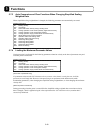
Contact output signals Total 6 points
OUT_DRDY 1 Driver ready
Turns ON when it is not in the error
status.
OUT_SEDY 1 Servo ready
Turns ON when it is in the servo ready
status.
OUT_OVER 1 Over signal
Turns ON when position deviation
overflow or excessive velocity occurs.
OUT_XOVL 1 Overload signal Turns OFF when overload occurs.
OUT_COIN 1 Position settling signal
Turns ON when the position deviation
is within the settling width.
OUT_BUSY 1 Busy
The status where operation cannot be
performed according to the pulse train
position command.
Position command pulse input signals
Total 2 pairs
PUA_IN ±
1 Position command pulse 1
PLS, UP, or A, depending on the
setting
SDB_IN ±
1 Position command pulse 2
SIGN, DOWN, or B, depending on the
setting
Position current pulse output signals
Total 3 pairs
UA_OUT ±
1 Position current pulse 1 UP or A, depending on the setting
DB_OUT ±
1 Position current pulse 2
DOWN or B, depending on the setting
Z_OUT ±
1 Origin pulse
Analog input Total 1 pair
CRNT_LMT_IN ±
1 Current limit 0V: 0% to 10V: 100%
6