


5-4
Functions
5
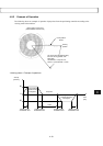
5.2.2 Test Operation
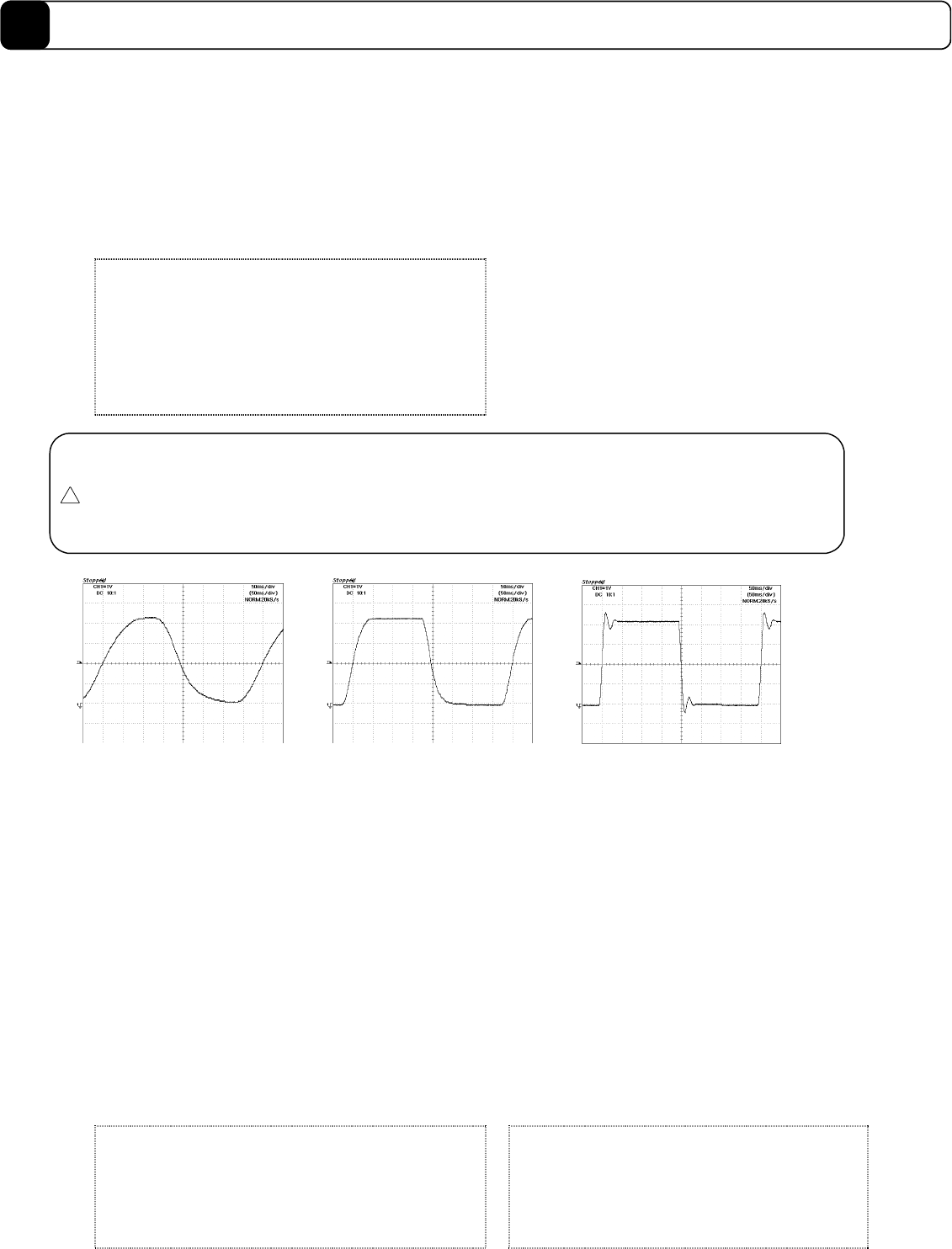
This operation generates a 2.5Hz square wave and uses it as position command signal for adjustment of the
control part. Set the analog monitor to test operation response to measure the response waveform on the
oscilloscope.
The position feed forward, velocity feed forward, and acceleration feed forward are set to 0 internally during the
test operation.
The settling wait function is not performed at the end of the test operation.
[Related parameters]
#31 Operation width under testing mode
#50 Position control bandwidth 1
#48 Position control bandwidth 2
#51 Velocity control bandwidth 1
#49 Velocity control bandwidth 2
#53 Position integral limiting value
#70 Analog monitor selection
#72 Test operation monitoring gain (analog monitor)
Caution
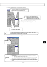
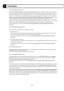
• Obtain the fastest possible rise time of the response waveform and make adjustments so that
overshoot will not occur.
• The closer the position control bandwidth and velocity control bandwidth are, the more the waveform
will oscillate.
• If the inertia and weight of the load are large, the oscillations may be eliminated by setting the
position integral limiting value to a small value.
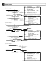
If the velocity control bandwidth cannot
be increased any further, the position
control bandwidth should be decreased
Make adjustments until this waveform
is reached
Increase the position control bandwidth.
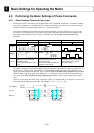
5.2.3 Auto-Tuning Operation
This operation makes the rotor oscillate, measures the inertia and weight of the load, and automatically sets the
parameters for the control part.
It accelerates/decelerates with half the rated torque and rated thrust of the motor, and measures the inertia and
weight of the load from the velocity changes at that time. The result of the measurement is written to the #155
Load inertia/load mass parameter.
From the measured inertia and weight of the load, it adjusts the position control bandwidth, velocity control
bandwidth, and position integral limiting value according to the setting value of the #38 Servo stiffness
settings parameter. For the position control bandwidth and the velocity control bandwidth, the results are
reflected in the parameters on the side selected by the controller interface (see Section 6.5.2, “Position Control
Bandwidth Selection FN” and Section 6.5.3, “Velocity Control Bandwidth Selection GAIN). It does not adjust
position feed forward, velocity feed forward, and acceleration feed forward.
The settling wait function is not performed at the end of the auto-tuning operation.
[Related parameters] [Auto-set parameters]
#32 Operation width under Auto-tuning
#33 Maximum deceleration under Auto-tuning
#34 Initializing the deceleration time while under Auto-
tuning
#37 Auto-tuning repeat count
#38 Servo stiffness settings
#50 Position control bandwidth 1
#48 Position control bandwidth 2
#51 Velocity control bandwidth 1
#49 Velocity control bandwidth 2
#53 Position integral limiting value
#155 Load inertia/load mass
!
!!
!