


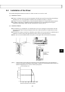
3-8
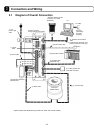
Connection and Wiring
3
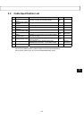
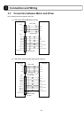
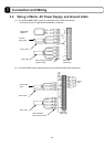
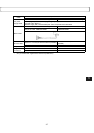
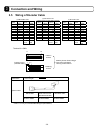
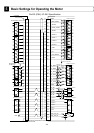
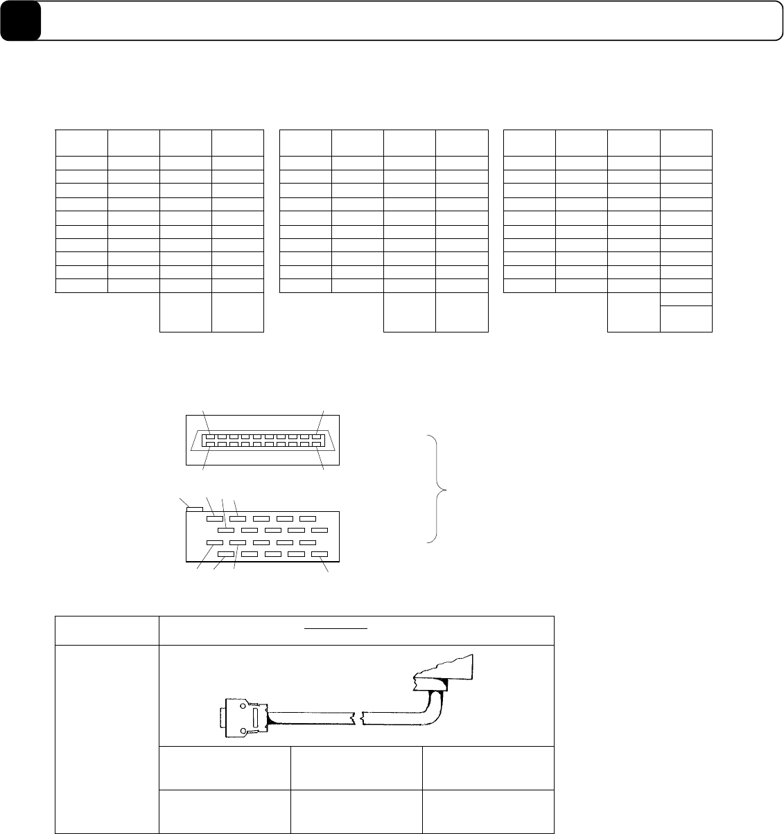
3.5 Wiring of Encoder Cable
(1) DM1004B/C motor
(2) DM series motor
(other than the one described to the left)
(3) DR series motor
Pin #
Signal
name
Pin #
Signal
name
Pin #
Signal
name
Pin #
Signal
name
Pin #
Signal
name
Pin #
Signal
name
1 + 10 V 11 - 1 + 10 V 11 - 1 - 11 +S180
2 - 12 GND 2 - 12 GND 2 +S0 12 -
3
θSIG 0
13 - 3
θSIG 0
13 ECLK- 3 - 13 -
4 - 14 GND 4 ECLK+ 14 GND 4 - 14 -
5
θ SIG 1
15 - 5
θSIG 1
15 - 5 - 15 -S180
6 - 16 GND 6 - 16 GND 6 -S0 16 -
7 ECLK+ 17 - 7 - 17 - 7 - 17 -C180
8 - 18 ECLK- 8 - 18 - 8 -C0 18 -
9 - 19 - 9 ZERO+ 19 ZERO- 9 - 19 -
10 - 20 - 10 - 20 - 10 +C0 20 +C180
FG
Chassis
ground
Shielded
cable
Chassis
ground
Shielded
cable
Chassis
ground
Shielded
cable
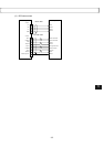
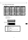
Terminal for <CN2>
2011
1 32
1
11 1312
20
10
Chassis ground
(shielded cable)
Insertion
surface
Soldering
surface
Made by Honda Tsushin Kogyo
Connector: PCR-S2OF
Housing: PCR-LS20LA1
Electric wire
specification
! 0.2 mm
2
multiple-core twisted pair batch shielded cable, 30 m or
less in length*
DM1004B/C
DM series motor
(other than the ones
described to the left)
DR series motor
Optional cable
CE7900C-""" CE7900M-""" CE7900R-"""
* Within 10 m only for small-diameter/flat types (DM1004B/C).