


3-10
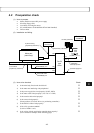
Connection and Wiring
3
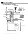
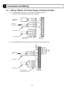
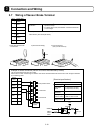
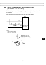
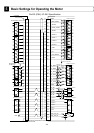
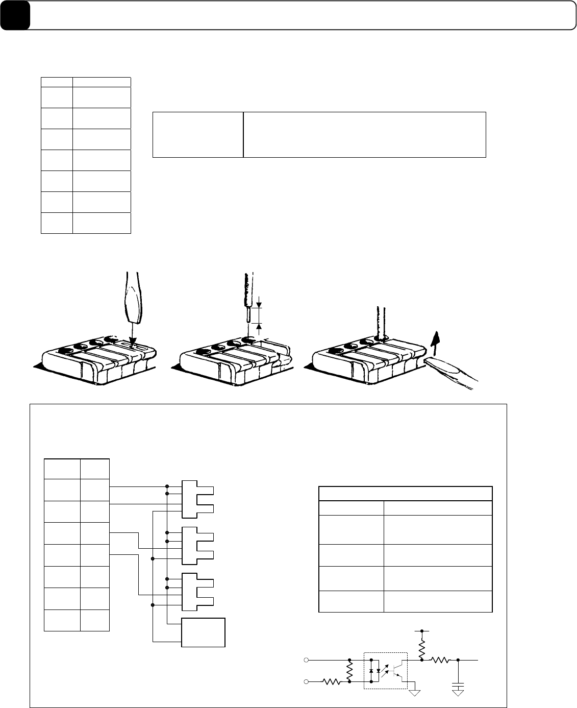
3.7 Wiring of Sensor Brake Terminal
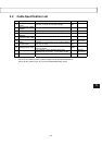
Pin # Signal name
1COMP0
2XORG
3XOTD
4XOTU
5(NC)
6 XBRKP
7 XBRKN
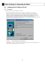
10mm
1) Push down the lever with
a screwdriver.
2) Insert the wire deeply.
3) Push up the lever
(until you hear the click)
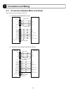
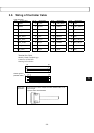
Pin #
7
6
5
4
Signal
name
XBRKN
XBRKP
(NC)
XOTU
3
2
XOTD
XORG
1COMP0
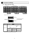
The recommended sensor logic is B contact.
Set the sensor to OFF when the light is shielded. The sensor described above will be set to OFF when the light is shielded
by the following result.
Home position sensor
(-) Over travel
(+) Over travel
DC power
supply
1
2
3
4
1
2
3
4
1
2
3
4
+
-
Example of sensor connection (sensor: EE-SX670 manufactured by Omron)
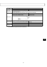
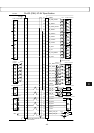
Rated voltage
Input specifications
12~24VDC (±10%)
Rated input
current
4.1 mA/point (at 12 VDC)
8.5 mA/point (at 24 VDC)
Input
impedance
3.0kΩ
Operating voltage
(relative to COMP*)
At OFF: 3.0 VDC or less
At ON: 9.0 VDC or more
Allowable
leakage current
OFF is guaranteed at 1.0
mA or less.
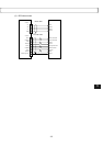
470Ω
2.7kΩ
COMP0
XORG
XOTD
XOTU
100kΩ
10kΩ
0.01μF
Vcc
PS2805
[Electrical specifications]
Electric wire
specification
! 0.3 to 0.75 mm
2
, electric wire coating with 10 mm of the core
exposed at the tip
! If a twisted wire is used, the diameter of the strand should be
φ 0.18 or larger.
See the panel surface of the driver for the pin numbers.
<TB2> Made by Sato Parts (ML1900H)