


6-6
Control Interfaces
6
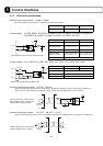
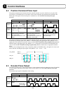
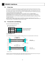
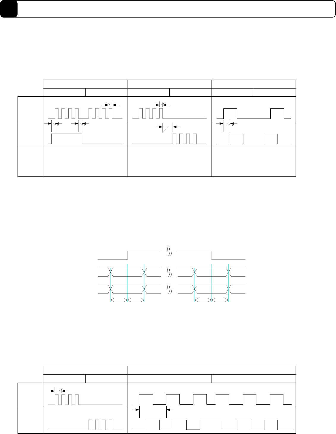
6.2 Position Command Pulse Input
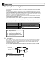
The position command value instructed from the controller interface is given to the driver by any pair of the
(PLS, SIGN), (UP, DOWN) and (A, B) signals, which is then reflected in the command unit command value.
Which pair of the signals will be used to give a command is set with the #204 Command pulse type
parameter.
+ direction - direction + direction - direction + direction - direction
(PLS, SIGN) (UP, DOWN) (A, B)
SIGN
PLS
PUA_IN
±
SDB_IN
±
UP
The signal should be H when active
(status for flowing current to the
driver photocoupler).
As for the PLS, it should be L when
normal.
DOWN
A
B
Caution
3
µ
s min 3
µ
s min
150ns min
The signal should be H when active
(status for flowing current to the
driver photocoupler).
As for both the UP and DOWN, they
should be L when normal.
150ns min
6
µ
s min
The signal should be H when active
(status for flowing current to the
driver photocoupler).
300
µ
s min
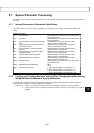
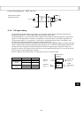
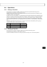
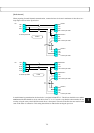
The position command value instructed from the controller interface can change the weight of a single pulse on
the interface by the input signal “PLS_DIRECT.” When the status of the input signal “PLS_DIRECT” is 0, a
single pulse on the interface becomes the value set with the #207 Simplified scaling weighted data parameter.
While the status of the input signal “PLS_DIRECT” is 1, a single pulse on the interface is independent of the
value set with the #207 Simplified scaling weighted data parameter, and becomes a single pulse inside the
driver.
However, do not change the status of any of the (PLS, SIGN), (UP, DOWN) and (A, B) signals for 2 msec each
before and after switching the input signal “PLS_DIRECT” (off →on, on → off).
PLS_DIRECT
PUA_IN
±
Unchanged
Status 1
Status 0
SDB_IN
±
2 msec
or more
2 msec
or more
2 msec
or more
2 msec
or more
Unchanged
Unchanged
Unchanged
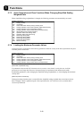
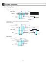
6.3 Encoder Pulse Output
The position current value is output from the driver via the controller interface by either pair of the (UP, DOWN)
or (A, B) signals. Which pair of the signals will be used to output is set with the #205 Monitor pulse type
parameter.
The encoder origin signal is independent of this setting.
+ direction - direction + direction
(UP, DOWN) (A, B)
UA_OUT
±
DB_OUT
±
UP
DOWN
A
B
3MHz max
750kHz max
- direction