6-5
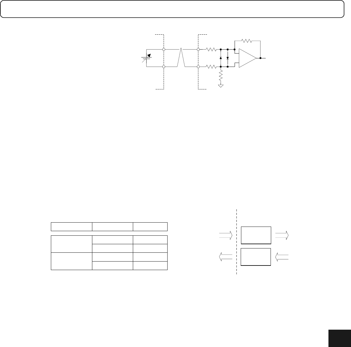
[Current limit analog input] CRNT_LMT_IN
±
Current 100% at 10 VDC
Current 0% at 0 VDC
Controller
+
-
0 to 10VDC
CRNT_LMT_IN+
200k
Ω
200k
Ω
CRNT_LMT_IN-
6.1.4 I/O logic setting
For the contact input and contact output signals, it is possible to set the physical I/O status and the logical
relationship of the driver’s internal signal status in both contact and bit units.
The input signals IN*** are processed via the I/O logical conversion and are then expressed as a logical input
signal ***. If the signal status is reached, it is expressed as 1 and if the status is not reached, expressed as 0.
A logical output signal *** is expressed as 1 if the status is reached and 0 if the status is not reached. After
conversion via the I/O logical setting, it becomes an output signal OUT_***.
The I/O logical settings at the time of shipment from the factory are set to positive logic for all input and output
signals. In other words, the internal input and output signals are set to 1 when the corresponding contact points
are turned ON. By setting the I/O logical setting for IN_SERVO to negative logic using the PC utility, it is
possible to connect a PLC interface in the same state as it was shipped from the factory. As a result, an RS232C
interface can be used to confirm basic operations.
Refer to Chapter 8 “DrvGII PC Utility” for a description of how to set the I/O logic.
Logic setting
Positive logic
setting
Bit I/O status
0
1
1
Logic signal
Status 0
Status 1
Status 0
Negative logic
setting
0 Status 1
Bit input
(IN_***)
Bit output
(OUT_***)
Driver's internal
processing
Processing
by logic
setting
Processing
by logic
setting
Logical input
signal (***)
Logical
output signal
(***)
6


