System Control Coprocessor
ARM DDI 0363E Copyright © 2009 ARM Limited. All rights reserved. 4-41
ID013010 Non-Confidential, Unrestricted Access
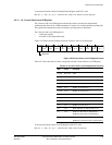
To access the Auxiliary Control Register, read or write CP15 with:
MRC p15, 0, <Rd>, c1, c0, 1 ; Read Auxiliary Control Register
MCR p15, 0, <Rd>, c1, c0, 1 ; Write Auxiliary Control Register
ARM recommends that any instruction that changes bits [31:28] or [7] is followed by an
ISB
instruction to ensure that the changes have taken effect before any dependent instructions are
executed.
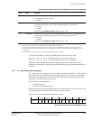
c15, Secondary Auxiliary Control Register
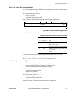
The Secondary Auxiliary Control Register is:
• a read/write register
• accessible in Privileged mode only.
Note
This register is implemented from the r1pm releases of the processor. Attempting to access this
register in r0pm releases of the processor results in an Undefined Instruction exception.
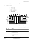
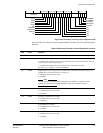
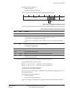
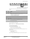
Figure 4-29 on page 4-42 shows the arrangement of bits in the register.
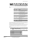
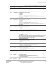
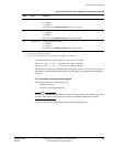
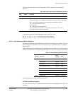
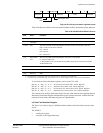
[2] B1TCMECEN B1TCM external error enable:
0 = Disabled
1 = Enabled.
The primary input ERRENRAM[2] defines the reset value.
[1] B0TCMECEN B0TCM external error enable:
0 = Disabled
1 = Enabled.
The primary input ERRENRAM[1] defines the reset value.
[0] ATCMECEN ATCM external error enable:
0 = Disabled
1 = Enabled.
The primary input ERRENRAM[0] defines the reset value.
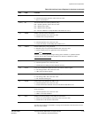
a. See Dual issue on page 14-34
b. See Configuration signals on page A-4.
c. This bit is only supported if parity error generation is implemented in your design.
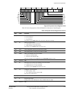
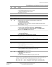
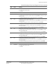
Table 4-24 Auxiliary Control Register bit functions (continued)
Bits Field Function


