Debug
ARM DDI 0363E Copyright © 2009 ARM Limited. All rights reserved. 11-15
ID013010 Non-Confidential, Unrestricted Access
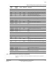
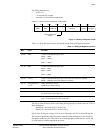
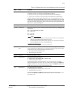
[24] InstrCompl Instruction complete read-only bit. This flag determines whether the processor has
completed execution of an instruction issued through the APB port.
0 = processor is currently executing an instruction fetched from the ITR Register
1 = processor is not currently executing an instruction fetched from the ITR Register.
When the APB port reads the DSCR and this bit is clear, then a subsequent write to the
ITR Register is ignored unless DSCR[21:20] is not equal to 0. If DSCR[21:20] is not equal
to 0, the ITR write stalls until the processor completes execution of the current instruction.
If the processor is not in debug state, then the value read for this flag is Unpredictable. The
flag is set to 1 on entry to debug state.
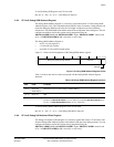
[23:22] Reserved RAZ on reads, SBZP on writes.
[21:20] DTR access DTR access mode. You can use this field to optimize DTR traffic between a debugger and
the processor.
b00 = Non-blocking mode, the default
b01 = Stall mode
b10 = Fast mode
b11 = Reserved.
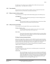
Note
• This field only affects the behavior of DSCR, DTR, and ITR accesses through the
APB port, and not through CP14 debug instructions.
• Non-blocking mode is the default setting. Improper use of the other modes might
result in the debug access bus becoming deadlocked.
See DTR access mode on page 11-17 for more information.
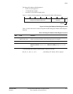
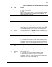
[19] Discard imprecise
abort
The Discard imprecise abort bit is set when the processor is in debug state and is cleared
on exit from debug state. While this bit is set, the processor does not take imprecise Data
Aborts. However, the sticky imprecise Data Abort bit is set to 1.
0 = do not discard imprecise Data Aborts
1 = discard imprecise Data Aborts.
[18-16] Reserved RAZ on reads, SBZP on writes.
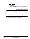
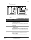
[15] Monitor mode The Monitor debug-mode enable bit:
0 = Monitor debug-mode disabled, this is the reset value
1 = Monitor debug-mode enabled.
If Halting debug-mode is enabled through bit [14], then the processor is in Halting
debug-mode regardless of the value of bit [15]. If the external interface input DBGEN is
LOW, this bit reads as 0. The programmed value is masked until DBGEN is HIGH, and
at that time the read value reverts to the programmed value.
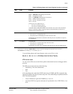
[14] Halting mode The Halting debug-mode enable bit:
0 = Halting debug-mode disabled, this is the reset value
1 = Halting debug-mode enabled.
If the external interface input DBGEN is LOW, this bit reads as 0. The programmed value
is masked until DBGEN is HIGH, and at that time the read value reverts to the
programmed value.
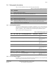
Table 11-10 Debug Status and Control Register functions (continued)
Bits Field Function


