Cycle Timings and Interlock Behavior
ARM DDI 0363E Copyright © 2009 ARM Limited. All rights reserved. 14-29
ID013010 Non-Confidential, Unrestricted Access
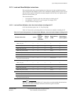
14.19 Floating-point register transfer instructions
This section describes the cycle timing behavior for the various VFP instruction which transfer
data between the VFP register file and the integer register file, including the system registers.
All source operands are Normal Regs, and the result latency for non-system register transfers is
always 1 cycle.
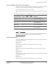
Instructions that write data from the integer register file to the VFP system registers (
FMXR
) are
blocking, that is, no subsequent instruction can start execution before the
FMXR
has completed
execution. Consequently, the
FMXR
instructions take six cycles to execute.
All transfers to and from the VFP system registers are also serializing. This means that if there
are any outstanding out-of-order-completion VFP instructions, the system register transfer
instruction will stall in the iss-stage until these instructions are complete.
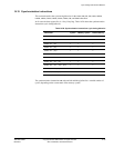
VFP instructions that complete out-of-order are
VMLA.F32
,
VMLS.F32
,
VNMLS.F32
,
VNMLA.F32
,
VDIV.F32
,
VSQRT.F32
,
VCVT.F64.F32
, and double-precision arithmetic and conversion instructions.
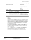
Table 14-24 shows the floating-point register transfer instructions cycle timing behavior.
Table 14-24 Floating-point register transfer instructions cycle timing behavior
Example instruction Cycles Result latency Comments
VMOV <Sn>, <Rt>
11 -
VMOV <Rt>, <Sn>
12 -
VMOV <Dn[x]>, <Rt>
11 -
VMOV.<dt> <Rt>, <Dn[x]>
12 -
VMOV <Sm>, <Sm1>, <Rt>, <Rt2>
11 -
VMOV <Rt>, <Rt2>, <Sm>, <Sm1>
12 -
VMOV <Dm>, <Rt>, <Rt2>
11 -
VMOV <Rt>, <Rt2>, <Dm>
12 -
VMSR <spec_reg>, <Rt>
6 - Blocking and serializing
VMRS <Rt>, <spec_reg>
12 Serializing
VMRS APSR_nzcv, FPSCR
1- Serializing


