


COPYRIGHT
©
1998 CANON INC. CANON NP7161/NP7160 REV.0 AUG. 1998 PRINTED IN JAPAN (IMPRIME AU JAPON)
6–5
CHAPTER 6 FIXING SYSTEM
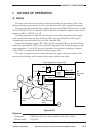
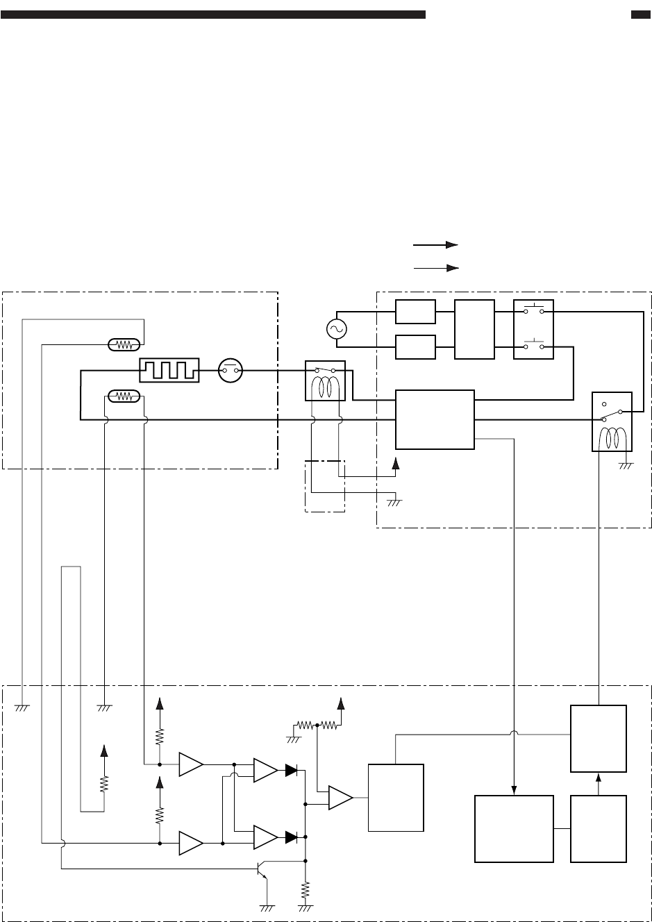
C. Error Detection Circuit
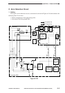
1. Outline
The copier’s error detection circuit is constructed as shown in Figure 6-104, and monitors the
following items for an error:
• Surface temperature of the upper fixing roller
• Activation of the fixing heater (H1)
Figure 6-104
DC controller PCB
Power supply PCB
HVT
Fixing assembly
TH2
TH2
TH1
TH1
HEAT_ERR
AC_24V_ON
TH1_DT
J108-3
-2
-4
-1
J109-2
-1
J106
-19
J106
-24
J212
-6
J212
-1
TSWH1
+5V
+5V
+5V
+5V
Buffer
Buffer
+
-
-
+
Gate
array
timer
Error
detection
circuit
IC119
CPU
IC113
Heater ON
detection
Converter
AC
driver
RL1
J201
-2
-1
J210
-1
-2
LF
DS1
RL
CB1
CB2
AC power line
DC signal line
+24V