


COPYRIGHT
©
1998 CANON INC. CANON NP7161/NP7160 REV.0 AUG. 1998 PRINTED IN JAPAN (IMPRIME AU JAPON)
10–83
CHAPTER 10 TROUBLESHOOTING
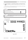
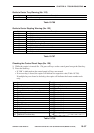
C. Using Adjust Mode and Function Mode
In adjust mode and function mode, the copier stores the settings made on the control panel in
the RAM on the DC controller PCB and use them to simulate the functions of conventional
variable resistors and switches.
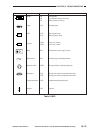
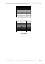
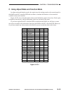
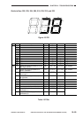
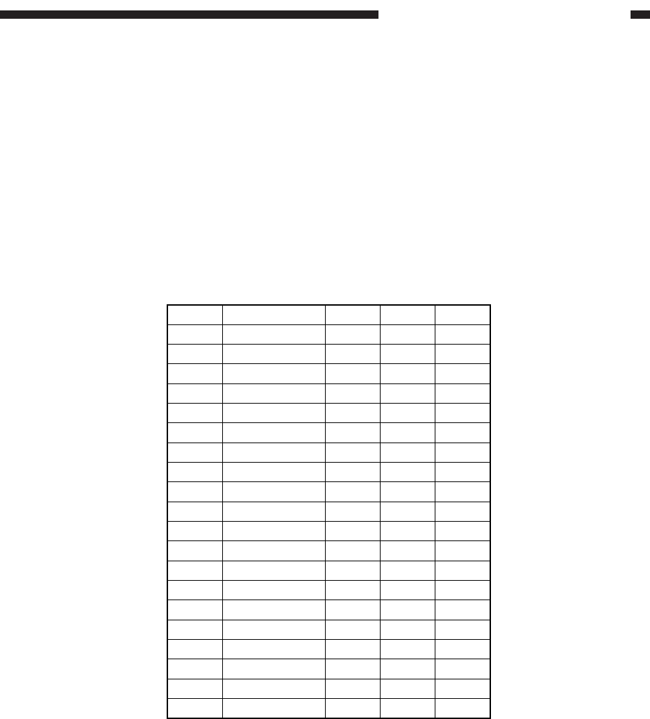
Figure 10-701 shows the information sheet stored behind the copier’s front door. Each copier
is adjusted at the factory, and the adjustment values are recorded in the sheet.
If you have replaced the DC controller PCB or initialized the RAM, you will have to enter
the values recorded in the information sheet into the RAM on the DC controller PCB. Moreover,
if you have entered any values newly in the field, be sure to record the value in this sheet.
Figure 10-701
AE_ADJ301
TYP
LMP_ADJ302
AE_SLOP303
REGIST305
LE_BLANK306
PG_RGST307
PG_BLANK308
TE_BLANK309
MF_ARCH319
CST1_ARCH320
CST2_ARCH321
LIGHT_5326
LNS_HP327
MIRR_HP328
LNS_TBL329
MIRR_TBL330
MLT_CL331
MLT_TMG
MODEL_SW
332
DOC_ST_L701
519