


COPYRIGHT
©
1998 CANON INC. CANON NP7160/NP7161 REV.0 AUG. 1998 PRINTED IN JAPAN (IMPRIME AU JAPON)
7–19
CHAPTER 7 EXTERNALS/AUXILIARY MECHANISMS
G. DC Controller PCB
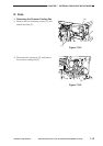
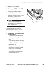
1. Removing the DC Controller PCB
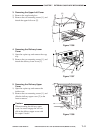
1) Remove the delivery lower cover.
2) Disconnect all connectors of the DC
controller PCB; then, free the harness
from the harness guide.
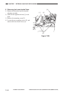
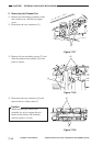
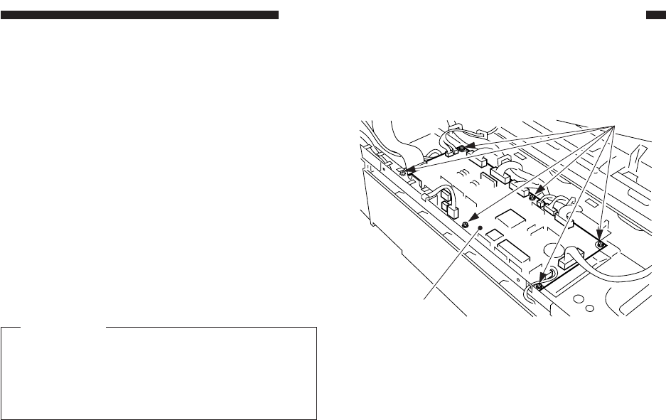
3) Remove the six mounting screws [1], and
remove the DC controller PCB [2]
together with the base plate.
Caution:
Take extra care not to damage the
harness whenever you are removing
the DC controller PCB.
The DC controller PCB is equipped with
a built-in battery (BAT101). Keep the
following in mind to prevent its both ends
from short circuiting and heating:
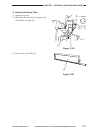
2. Points to Note When Replacing the
DC Controller PCB
• When sending the DC controller to the
workshop or the factory, put it in a
conducting bag intact with its base
plate.
Use a conducting bag whose one side is
transparent, and be sure that the face of
the DC controller PCB shows through
the transparent side.
• After replacement, make adjustments
and settings in service mode and make
settings in user mode once again.
• For settings in service mode, enter the
values recorded in the Service Label
stored behind the front door.
Figure 7-324
[2]
[1]