


2–16
COPYRIGHT
©
1998 CANON INC. CANON NP7161/NP7160 REV.0 AUG. 1998 PRINTED IN JAPAN (IMPRIME AU JAPON)
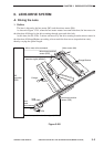
CHAPTER 2 BASIC OPERATION
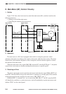
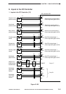
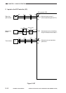
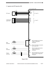
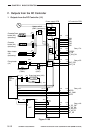
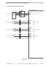
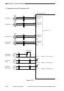
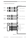
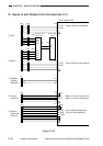
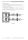
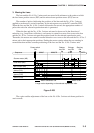
G. Inputs to and Outputs from Accessories (1/1)
Figure 2-113
DC controller PCB
+5V
J104
-A9
-A11
-A10
-A8
To Control
Card IV N
To ADF
CCD*
CCDT*
-4
-2
-3
-1
-4
-2
-3
-1
J120
-1
-3
-2
-4
J955
-1
-2
-3
-4
See the ADF Service Manual.
See the Sorter Service Manual.
See the Remote Diagnostic
Device II Service Manual.
When '0', control card turns on.
When '0', the card is detected.
DF-RXD
DF-TXD
J750
J754
-1
-2
-3
-4
-9
-10
-11
-12
-4
-2
-3
-1
-1
-2
-3
-4
J752
Accesory power
supply PCB
Power supply
PCB
J952
-1
-2
-3
-4
J206
-1
-4
J951
-1
-3
-1
-2
-3
-4
J753
To Sorter
To Cassette
Feeding
Module-C1
-4
-2
-3
-1
-4
-2
-3
-1
-1
-2
-3
-4
-9
-10
-11
-12
-4
-2
-3
-1
J120
-5
-7
-6
-8
ST-RXD
ST-TXD
J751
J755
-2
-4
-3
-1
J790
+24V
+5V
J121
-2
-7
-4
-5
-6
-1
-3
-8
To Remote
Diagnostic
Device II
AS_RXD
AS_CNTP
AS_TXD
-7
-2
-5
-4
-3
-8
-6
-1
J722
+24V1
+24V2
GND1
GND2
AC
AC
+24V1
+24V2
GND1
GND2
J122
J701