


COPYRIGHT
©
1998 CANON INC. CANON NP7161/NP7160 REV.0 AUG. 1998 PRINTED IN JAPAN (IMPRIME AU JAPON)
2–11
CHAPTER 2 BASIC OPERATION
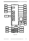
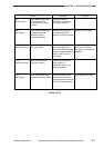
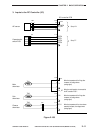
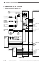
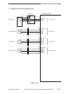
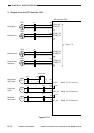
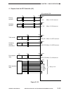
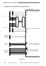
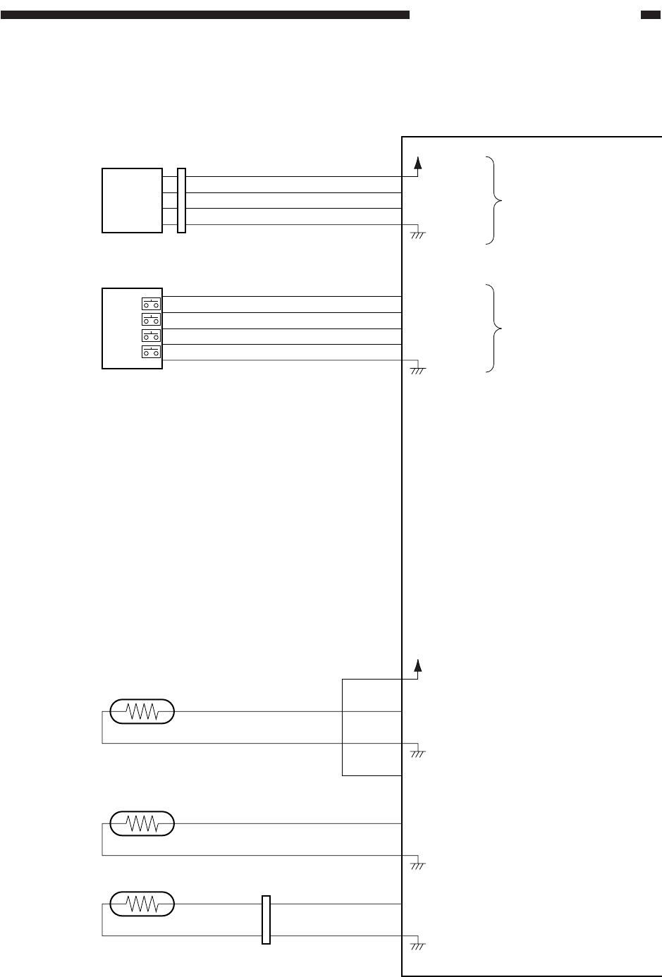
3. Inputs to the DC Controller (3/3)
Figure 2-108
DC controller PCB
+24V
+5V
J103
-A4
-A3
-A2
-A1
AE sensor
See p. 4-21.
AE_DATA
AE_REF
J16
-2
-3
-4
-5
-1
J110
-4
-3
-2
-1
-5
Cassette size
switch PCB
See p. 5-7.
CSTS1
CSTS2
CSTS3
CSTS0
-4
-3
-2
-1
-1
-2
-3
-4
J531
J108
-1
-2
-3
-4
Main
thermistor
TH1
When the temperature of the fixing roller
increases, the voltage lowers.
(analog signal)
TH1_DT
When the main thermistor is connected to
the DC controller PCB, '1'.
TH1
J109
-1
-2
Sub
thermistor
TH2
When the temperature of the fixing roller
increases, the voltage lowers.
(analog signal)
TH2
J112
-1
-2
Cleaner
thermistor
CLTH
When the temperature of the drum cleaner
assembly increases, the voltage lowers.
(analog signal)
TH3
SW651
SW652
SW653
SW654
-2
-1
-1
-2
J23