


CHAPTER 7 EXTERNALS/AUXILIARY MECHANISMS
7–4
COPYRIGHT
©
1998 CANON INC. CANON NP7160/NP7161 REV.0 AUG. 1998 PRINTED IN JAPAN (IMPRIME AU JAPON)
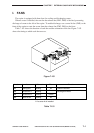
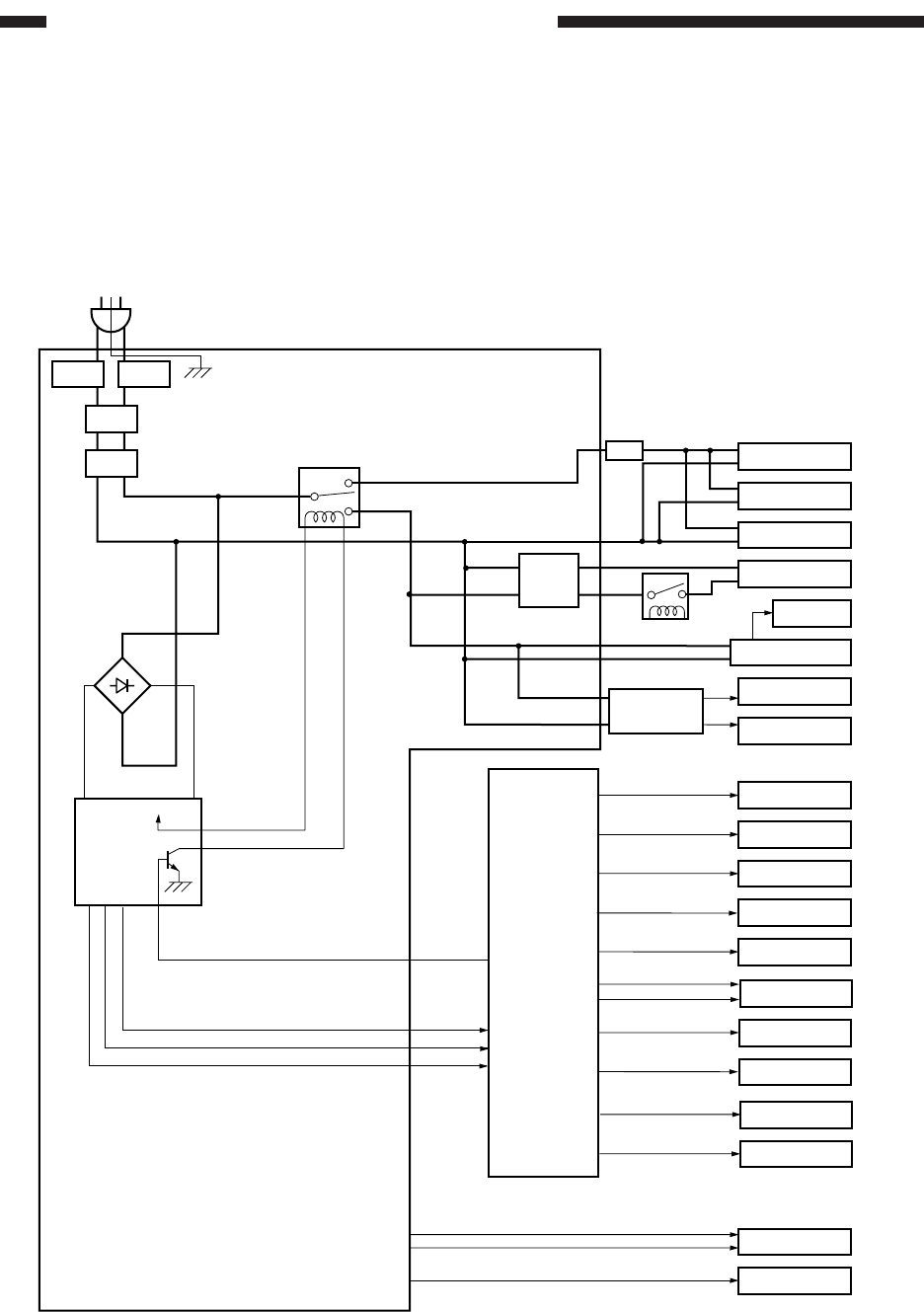
II. POWER SUPPLY
A. Outline of Power Supply
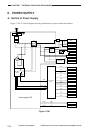
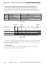
Figure 7-201 is a block diagram showing distribution of power inside the machine.
Figure 7-201
Cassette/Drum
heater
Accessory
cassette heater
Mirror heater
Fixing heater
Accessory power
supply PCB
AC
driver
RMT
CB2CB1
LF
RL
DS1
Sorter
AE sensor
Sensor
Fan
Motor
DC controller
PCB
Power supply PCB
Counter
HVT
Main motor
Blank-exposure
lamp
CC-IVN
Solenoid/Clutch
Lamp regulator PCB
ADF
+24V
+24V
+24V
+24V
+5VU
+24V
+24V
+24V
+24V
+24V
+5VU
+5VR
+5VU
+24V
+24V
+24V
LA1
SW1
Control panel PCB
+5VU
+5VR
+5VU
J208-1
-3
-4
J210-1
-8
J209-4
RL1
DC power
circuit
+24V
Pre-exposure lamp