


COPYRIGHT
©
1998 CANON INC. CANON NP7161/NP7160 REV.0 AUG. 1998 PRINTED IN JAPAN (IMPRIME AU JAPON)
8–17
CHAPTER 8 INSTALLATION
LED1LED2 LED3
2
1
LED5
LED6
LED4
IC6
SW1
SW4
SW3
6
1
BAT1
CN4
1
2
CN3 CN2
12345678
[12]
SW2
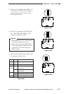
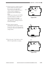
Figure 8-507
LED1LED2 LED3
2
1
LED5
LED6
LED4
IC6
SW1
SW4
SW3
6
1
BAT1
CN4
1
2
CN3 CN2
12345678
SW2
[13]
[14]
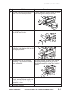
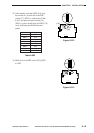
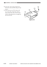
Setting
AII
OFF
ON
ON
OFF
ON
OFF
–
Description
selects push pulse for RDD circuit
confihuration
selscts dial pulse for RDD circuit
confihuration
sets dial pulse speed to 20 PPS
sets dial pulse speed to 10 PPS
reserved
Switch
SW3-1
SW3-2
SW3-3
SW3-4
SW3-5
SW3-6
Table 8-501
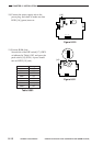
Figure 8-508
LED1LED2 LED3
2
1
LED5
LED6
LED4
IC6
SW1
SW4
SW3
6
1
BAT1
CN4
1
2
CN3 CN2
SW2
123456
[15]
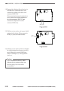
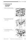
Figure 8-509
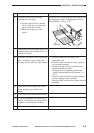
7) Shift bits 4 of the DIP switch (SW2) [12]
on the device’s PCB to ON (so that the
communication with the copier will be
IPC communication).
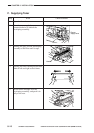
8) If IC6 [13] is mounted on the PCB, shift
bit 7 of the DIP switch (SW2) to ON;
otherwise, keep bit 7 at OFF.
Caution:
1.If the ROM (IC6) [13] is not mounted,
you need not mount one newly.
2.If you want to mount the ROM (IC6)
[13] for upgrading or replace it, be sure
to shift bit 7 of the DIP switch [14]
(SW2) to ON.
9) Set each bit of the DIP switch (SW3) [15]
as indicated in Table 8-501.