


COPYRIGHT
©
1998 CANON INC. CANON NP7161/NP7160 REV.0 AUG. 1998 PRINTED IN JAPAN (IMPRIME AU JAPON)
10–3
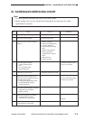
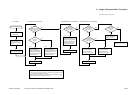
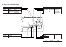
Pre-Checks Density Slope Adjustment Solid Black Density Adjustment Optimum Exposure Adjustment
Clean the charging wires.
Is there
a difference in density
between front and
rear?
Make two to three copies
of the Test Sheet (NA-3).
Make a copy.
Check the height of
the charging wire.
Set the setting of ‘U12:
density correction’ in
user mode to a standard
setting.
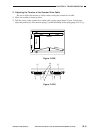
Turn the adjusting screw at
the rear of the primary
changing assembly counter-
clockwise and the adjusting
screw at the front clockwise
(1.0 mm max. each).
Turn the adjusting screw at
the rear of the primary
charging assembly clockwise
and the adjusting screw at
the front counterclockwise
(1.0 mm max. each).
Make a copy.
Turn the adjusting screw at
the front/rear of the primary
charging assembly counterc
lockwise so that the primary
charging wire is closer to
the photosensitive drum.
Increase the setting of
‘scanning lamp ON
voltage adjustment’
in service mode (326).
Decrease the setting of
‘scanning lamp ON
voltage adjustment’
in service mode (326).
Is the rear
lighter?
YES
YES
NO
NO
Is the density
of gray scale No. 1
too low (light)?
YES
NO
Make a copy.
Is the density
of gray scale No.
10 optimum?
Is the white
background
foggy?
NO YES
YES NO
Is the density
of gray scale No. 10 too
high (dark)?
YES
NO
See “Preventing Image
Faults.” (p. 10-32)
Perform AE
adjustment. (p. 10-19)
*1*2 *1*2
*1*2
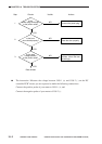
1: If there still is a difference after turning the adjusting screw 1.0 mm
each*, check the charging assembly, scanning lamp, and scanner for dirt.
*A full turn causes a change of 0.5 mm.
2: When turning the adjusting screw clockwise, be careful that the height
of the charging wire is not less than 10.0 mm.
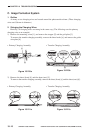
A. Image Adjustment Basic Procedure
Non-AE, Copy Density at 5