


CHAPTER 10 TROUBLESHOOTING
10–60
COPYRIGHT
©
1998 CANON INC. CANON NP7161/NP7160 REV.0 AUG. 1998 PRINTED IN JAPAN (IMPRIME AU JAPON)
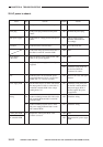
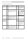
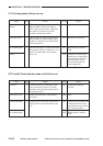
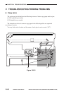
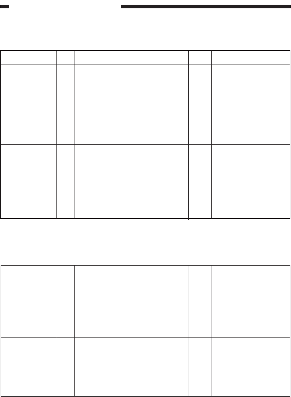
31.The fixing heater fails to turn on.
Thermal switch
(TSW1)
Fixing heater (H1)
DC controller PCB
Wiring
1
2
3
NO
NO
NO
YES
Turn off the power switch, and remove the
fixing assembly. Set the meter range to
“Ωx1.” Does the meter index swing when
the probes are connected across both
terminals of the thermal switch?
Turn off the power switch, and remove the
fixing assembly. Is there continuity when
probes are connected across both terminals
of the fixing heater?
Set the meter range to 30 VDC, and connect
the probes to J106-21 (+) and J105-4 (-) on
the DC controller PCB. Is the resistance
about 5 V?
Replace the thermal switch.
Replace the fixing heater.
Replace the DC controller
PCB.
Check the AC harness from
the DC power supply PCB to
the fixing heater. Check the
DC harness from the DC
controller PCB to the DC
power supply PCB.
Actions
ChecksStep
Cause
Yes/No
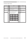
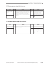
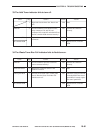
32.The Add Toner indicator does not flash/turn on.
Connector
Toner sensor (TS1)
Control panel PCB
DC controller PCB
1
2
3
NO
YES
NO
YES
Connect the connectors
securely.
End.
Check the wiring from the DC
controller PC to the control
panel PCB; if normal, replace
the control panel PCB.
Replace the DC controller
PCB.
Are the connector J15 of the toner sensor,
relay connectors J721 and J722, and the
connector J102 on the DC controller PCB
connected securely?
Replace the toner sensor. Is the problem
corrected?
Execute service mode ‘409’ (control panel
check). Does the Add Toner indicator turn
on?
Actions
ChecksStep
Cause
Yes/No