


CHAPTER 10 TROUBLESHOOTING
10–52
COPYRIGHT
©
1998 CANON INC. CANON NP7161/NP7160 REV.0 AUG. 1998 PRINTED IN JAPAN (IMPRIME AU JAPON)
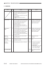
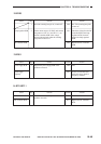
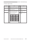
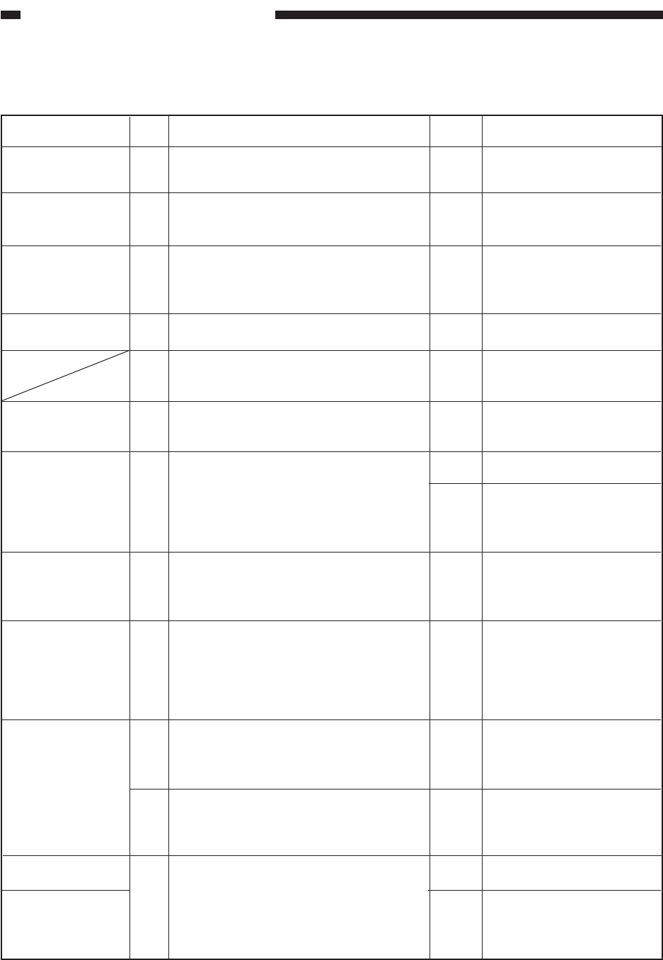
20.AC power is absent.
1
2
3
4
5
6
7
8
9
10
11
12
NO
NO
NO
NO
YES
YES
YES
NO
YES
NO
NO
NO
YES
NO
Is the power cord connected to the copier?
Is the power plug connected to the power
outlet?
Is the rated AC voltage present at the power
outlet?
Is the front door closed securely?
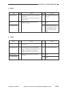
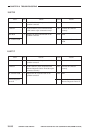
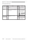
Is the rated voltage present between J204-1
and J204-3 on the DC controller PCB?
Press the button on the circuit breaker (CB1,
CB2). Is AC power supplied?
Replace the power supply cord. Is AC power
supplied?
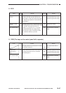
Is the fuse (FU1, FU2) on the DC power
supply PCB blown? (125 V, 5 A for 120 V
model; 250 V, 2 A for 230 V model)
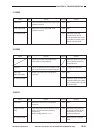
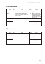
Set the meter range to 30 VDC, and connect
the meter probes to J105-4(+) and J105-5(-)
on the DC controller PCB. Is the voltage
reading about 5 V?
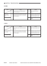
Is there continuity between J101-B15 on the
DC controller PCB and J403-1 on the DC
controller PCB?
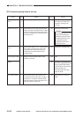
Is there continuity between J212-1 on the
DC power supply PCB and J106-2 on the
DC controller PCB?
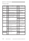
Replace the control panel PCB. Is the
problem corrected?
Connect the cord.
Connect the power plug.
This is not the copier’s
problem. Inform the user
accordingly.
Close the front door.
End.
End.
End.
Check the wiring of the AC
power line. Check the
connector for contact.
Remove the cause, and replace
the fuse.
Check the wiring from J105
on the DC controller PCB to
the power supply PCB; if
normal, replace the power
supply PCB.
Check the wiring.
Check the wiring.
End.
Replace the DC power supply
PCB.
Actions
ChecksStep
Cause
Yes/No
Power cord
Power plug
Main power supply
Front door
Circuit breaker
(CB1, CB2)
Power cord
Fuse
Power supply PCB
Wiring
Control panel PCB
DC controller PCB