


COPYRIGHT
©
1998 CANON INC. CANON NP7161/NP7160 REV.0 AUG. 1998 PRINTED IN JAPAN (IMPRIME AU JAPON)
6–1
CHAPTER 6 FIXING SYSTEM
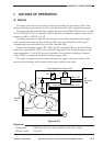
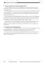
Figure 6-101
I. OUTLINE OF OPERATION
A. Outline
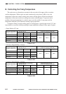
The upper roller and the lower roller of the fixing assembly and the delivery roller of the
delivery assembly are operated by the drive from the main motor (M1) coming through gears.
The upper roller has a built-in heater which is kept on during WMUP after power-on at 1000
W (120 V)/1050 W (230 V). Other than WMUP, the heater is subjected to phase control, and is
turned on at 805 w (120/230 V) or off.
The fixing temperature is detected with reference to the surface temperature of the upper
roller rear end detected by the main thermistor (TH1) and the sub thermistor (TH2), and is
communicated to the microprocessor on the DC controller PCB.
Based on the thermistor signal (TH1, TH2), the DC controller PCB turns on/off the fixing
heater drive signal (HEAT_DR) to turn on/off the fixing heater (H1), thereby keeping it at the
target temperature. To cut off AC power to the heater in the event of overheating, a thermal
switch (TSW1) is mounted at the front of the fixing upper roller.
The copier is designed to remove toner adhering to the upper or the lower roller; for this
reason, its heat discharge roller is kept in firm contact with the lower roller.
Reference:
Fixing heater: 1000 W for the 120 V model, 1050 W for the 230 V model.
Thermal switch: 230 ±10°C.
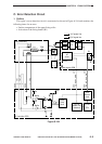
Fixing sub thermistor signal (TH2)
Fixing main thermistor signal (TH1)
HEAT
_
DR
HEAT
_
ERR
TSW1
RL1
+24V GND
Power
supply
PCB
H1
TH2
TH1
DC
controller
PCB
Heat discharge
roller
Fixing upper
roller
Pressure
roller
Delivery
roller
M1