


COPYRIGHT
©
1998 CANON INC. CANON NP7161/NP7160 REV.0 AUG. 1998 PRINTED IN JAPAN (IMPRIME AU JAPON)
3–9
CHAPTER 3 EXPOSURE SYSTEM
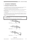
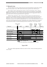
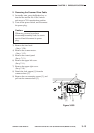
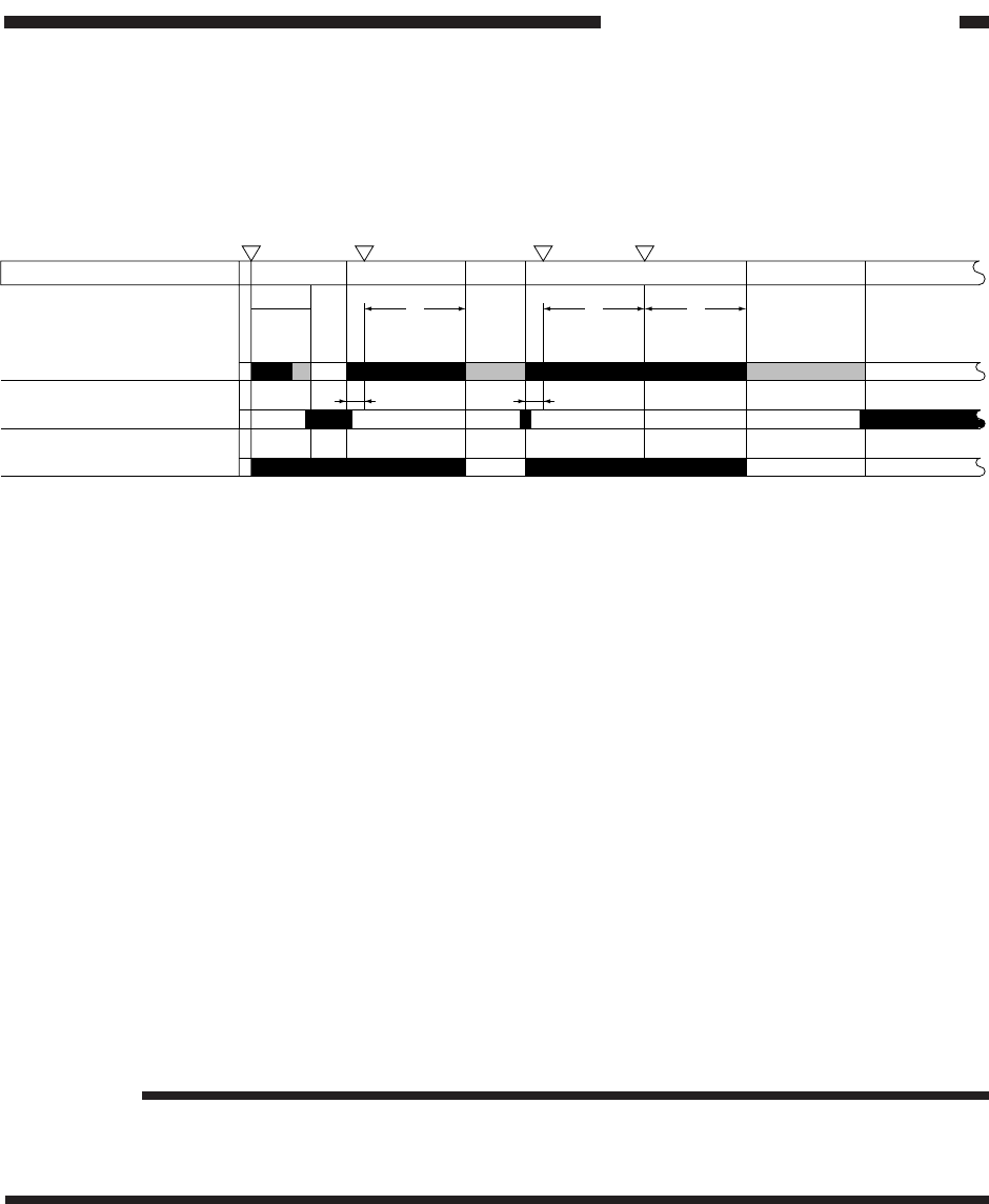
E. Scanner Movement in Page Separation Mode
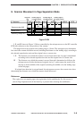
Figure 3-304
I, II, and III shown in Figure 3-304 are controlled by the microprocessor on the DC controller
PCB with reference to the wait position of the scanner.
The length from wait position to the leading edge is 18 mm. The microprocessor determines
how much the scanner should be moved (including the distance to the leading edge) according to
the selected reproduction ratio and the original size or cassette size.
I, II : The distance over which the scanner is moved forward for the 1st page is determined
according to the selected reproduction ratio and the original size or cassette size.
III : The distance over which the scanner is moved forward is determined as follows: the
microprocessor divides the detected original size by 2, and assumes the result of the
division to be the middle of the original (assuming the middle to be the leading edge
of the 2nd page).
If original size detection is not performed, the microprocessor uses the cassette size when
determining the distance over which the scanner should be moved.
Reference:
The copier does not require paper size registration for the multifeeder. For this reason, it
cancels Page Separate mode if the Start key is pressed after selecting the multifeeder.
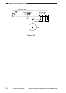
Start key
ON
Leading edge of
1st page (original)
Leading edge of
1st page (original)
Leading edge of
2nd page (original)
FW RV
LSTRSCRV2SCFW2
SCRV2
SCFW1INTR
AER
Sequence
Scanner motor (M2)
Scanner home position
sensor (PS1)
Scanning lamp (LA1)
18mm
I
18mm
II III