


COPYRIGHT
©
1998 CANON INC. CANON NP7161/NP7160 REV.0 AUG. 1998 PRINTED IN JAPAN (IMPRIME AU JAPON)
3–7
CHAPTER 3 EXPOSURE SYSTEM
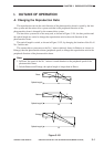
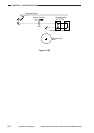
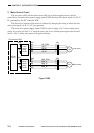
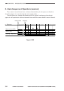
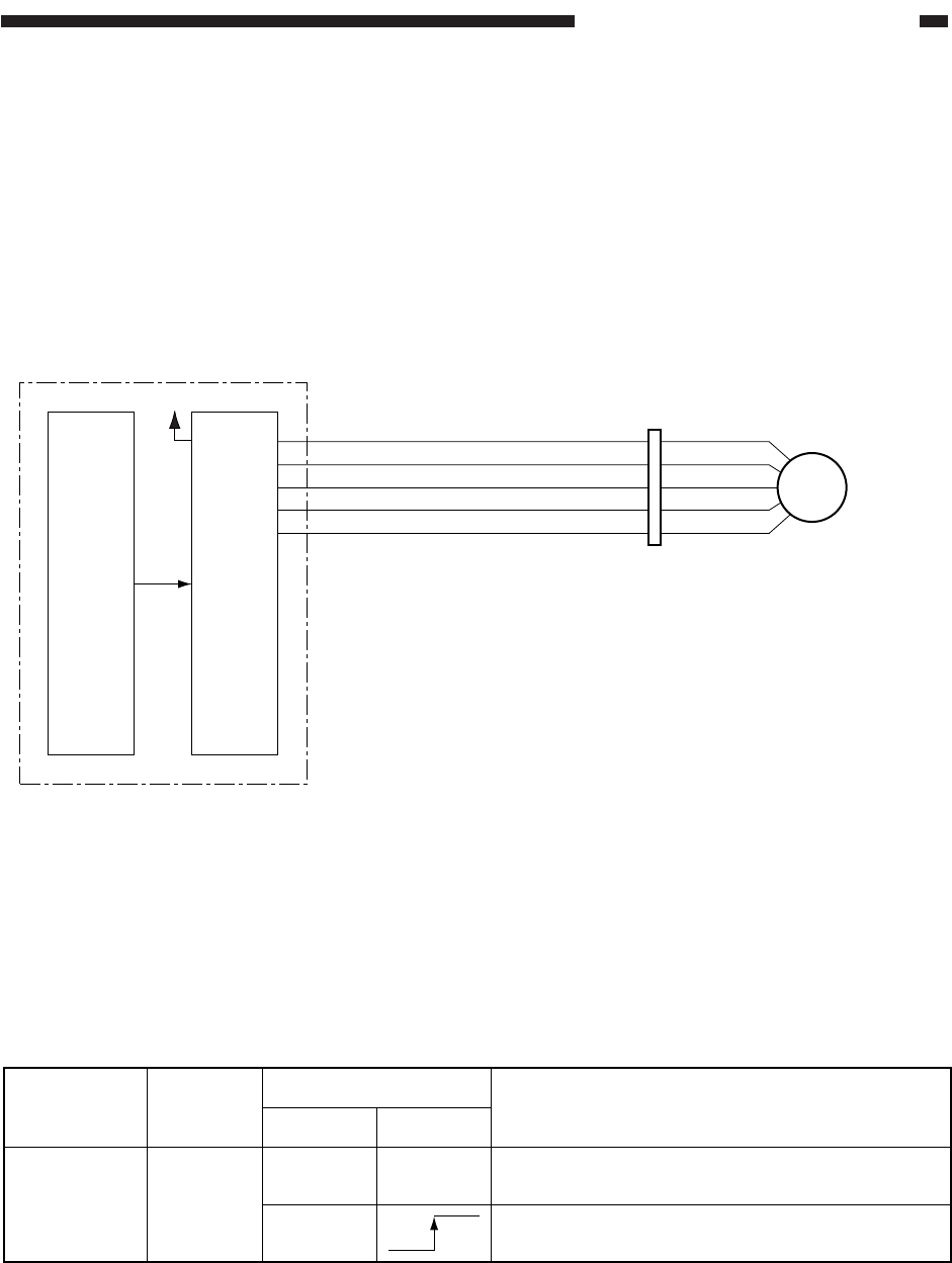
B. Scanner Motor Control Circuit
The scanner motor (M2) is a 4-phase stepping motor, and is controlled by four pulse signals
(SC_A, SC_B, SC_A*, SC_B*) generated by the DC controller PCB.
The scanner motor is turned on/off and its direction of rotation are controlled by changing
the timing at which these four pulse signals are generated. The speed of rotation, on the other
hand, is controlled by switching the current supplied to the scanner motor.
Figure 3-302
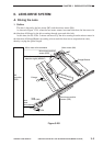
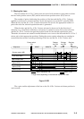
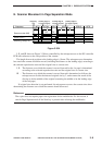
C. Relationship between Scanner Sensor and Signals
Table 3-301
Scanner
home position
sensor (PS1)
• The scanner is at home position.
• The scanner has reached home position.
Sensor Signal
Scanner
Foward Reverse
SCHP
Description
-3
-1
-4
-2
-5
J104
-A3
-A5
-A2
-A4
-A1
Scanner
motor
SC_A
SC_COM
SC_A*
SC_B
SC_B*
J37
M2
Scanner
motor
control
circuit
DC controller PCB
+24V
(IC117)
IC119
(CPU)