


COPYRIGHT
©
1998 CANON INC. CANON NP7161/NP7160 REV.0 AUG. 1998 PRINTED IN JAPAN (IMPRIME AU JAPON)
4–3
CHAPTER 4 IMAGE FORMATION SYSTEM
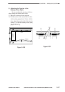
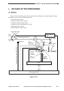
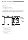
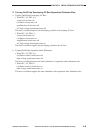
C. Controlling the Intensity of the Scanning Lamp
1. Outline
Figure 4-103 shows the circuit used to control the intensity of the scanning lamp, and the
circuit has the following functions:
1. Turning on/off the scanning lamp
2. Controlling the intensity of the scanning lamp
• controlling the light to a specific intensity against fluctuations in power supply voltage
Lamp regulator
PCB
Power supply
PCB
DC controller
PCB
+5V
LMPDR
Scanning lamp
(LA1)
Thermal fuse
(FU1)
J501
-1
-3
J203
-1
-3
J501
-4
-6
J503
-1
-2
-3
-4
-5
J211
-5
-4
-3
-2
-1
J106
-4
-8
-6
AC_24V_ON
J106
-24
J106
-24
J212
-21
-17
-19
Control
circuit
Drive
circuit
LMP_PWM
LMPDT
Error
detection
circuit
Lamp
ON
detection
IC113
IC119
(CPU)
RL
+24V
Figure 4-103