


2–8
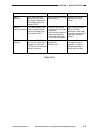
COPYRIGHT
©
1998 CANON INC. CANON NP7161/NP7160 REV.0 AUG. 1998 PRINTED IN JAPAN (IMPRIME AU JAPON)
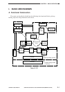
CHAPTER 2 BASIC OPERATION
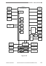
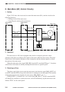
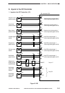
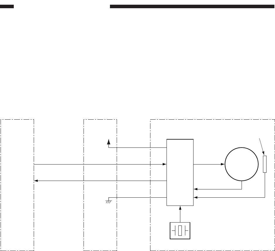
D. Main Motor (M1) Control Circuitry
1. Outline
Figure 2-105 shows the circuit used to control the main motor (M1), and the circuit has the
following functions:
• Turning on and off the main motor.
• Controlling the rotation of the main motor.
Figure 2-105
2. Operation
The main motor is a DC motor equipped with a built-in clock pulse generator, which
generates clock pulses according to the rotation of the motor while the motor rotates. The phase
control drive circuit matches the phases of the clock pulses and the reference signals to control
the rotation of the main motor.
When the main motor drive signal (MM_DR) from the DC controller PCB goes '1', the phase
control drive circuit turns on, thereby rotating the main motor at a specific speed.
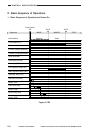
3. Detecting an Error
The phase control drive circuit sends the main motor lock detection signal (MM_LKDT*)=0
to the DC controller PCB as long as the main motor is rotating at a constant speed. If the rotation
of the main motor becomes irregular for some reason, MM_LKDT* goes '1'.
If MM_LKDT*=1 continues for 1 sec or more when MM_DR is '1', the DC controller PCB
will identify the condition as a main motor error, and will immediately stop the main motor and
indicate "E010" on the control panel.
J106
-17
-16
Main motor
Drive
current
Hall IC output
DC controller
PCB
J209
-4
-2
-1
-3
J212
-8
MM
–
DR
MM
–
LKDT* -9
J601
-4
-2
-1
-3
Power supply
PCB
+24V
M1
Phase
control
drive
circuit
Reference signal
Clock pulse
generator
Clock pulse