


CHAPTER 6 FIXING SYSTEM
6–12
COPYRIGHT
©
1998 CANON INC. CANON NP7161/NP7160 REV.0 AUG. 1998 PRINTED IN JAPAN (IMPRIME AU JAPON)
[2]
[3]
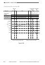
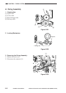
Figure 6-213
[1]
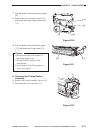
Figure 6-216
[2]
[1]
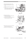
Figure 6-214
[A]
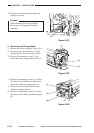
Figure 6-215
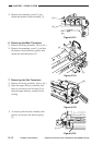
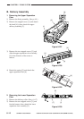
3) Remove the mounting screw [2], and
detach the thermal switch assembly [3].
6. Removing the Main Thermistor
1) Remove the fixing assembly. (See p. 6-8.)
2) Remove the mounting screw [1], and free
the harness from the harness guide; then,
detach the main thermistor [2].
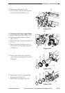
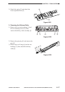
7. Removing the Sub Thermistor
1) Remove the fixing assembly. (See p. 6-8.)
2) Open the upper delivery assembly, and
insert a screwdriver into the hole [A] to
keep the upper delivery assembly from
closing.
3) As shown, pick the hook assembly with
pincers, and remove the tension spring
[1].