


COPYRIGHT
©
1998 CANON INC. CANON NP7161/NP7160 REV.0 AUG. 1998 PRINTED IN JAPAN (IMPRIME AU JAPON)
4–17
CHAPTER 4 IMAGE FORMATION SYSTEM
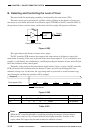
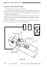
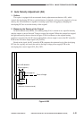
Figure 4-205
DC controller PCB
Cleaning blade
Waste toner feeding
screw
Photosensitve drum
Flag
PS8
Waste toner feeding screw locked detection signal (TRQMLDT)
Main motor drive command
Gear A
M1
Spring clutch
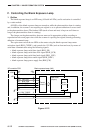
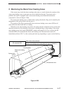
C. Monitoring the Waste Toner Feeding Screw
If the waste toner inside the drum cartridge cakes and, as a result, hinders the rotation of the
waste toner feeding screw, waste toner can start to leak from the pipe. To prevent such a
problem, the copier is equipped with a waste toner feeding screw detection mechanism
constructed as shown in Figure 4-206.
The waste toner feeding screw is linked with a spring clutch and a flag, and is rotated by the
engagement of the spring clutch with the gear A.
The rotation of the flag is monitored by the waste toner feeding screw sensor (PS8) at all
times while the main motor (M1) is rotating.
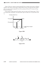
When the waste toner feeding screw locks, the spring clutch is subjected to force in the axial
direction and moves in the direction of the arrow, causing the flag to stop rotating. If the waste
toner feeding screw lock signal (TRQMLDT) remains unchanged for 0.5 sec or more, the DC
controller PCB will assume that the waste toner feeding screw became locked, and will
immediately indicate ‘E013’ on the control panel and stop responding to a press on the Start key.