


COPYRIGHT
©
1998 CANON INC. CANON NP7161/NP7160 REV.0 AUG. 1998 PRINTED IN JAPAN (IMPRIME AU JAPON)
CHAPTER 10 TROUBLESHOOTING
10–47
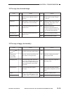
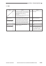
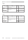
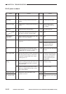
8. E031
Accessory counter
(CNT2)
Accessory counter
(CNT2)
DC controller PCB
1
2
NO
YES
NO
Turn off the power switch, and disconnect
J102 from the DC controller PCB. Set the
meter range to 1 KΩ, and connect the probes
to J102-A13 and J102-A12. Is the resistance
about 500 Ω?
Connect J102 to the DC controller PCB, and
turn on the power switch. Set the meter range
to 30 VDC, and connect the probes to
J102A13 (+) and J102-A12 (-) on the DC
controller PCB. Does the voltage change
from about 0 to about 24 and then to about
0 V when the Start key is pressed?
Check the wiring from the DC
controller PCB to the counter;
if normal, replace the counter.
Replace the counter.
Replace the DC controller
PCB.
Actions
ChecksStep
Cause
Yes/No
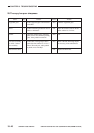
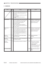
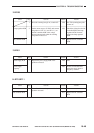
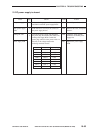
9. E202 (The keys on the control panel fail to operate.)
NO
NO
YES
Scanner home
position sensor
(PS1)
DC controller PCB
1
2
Does the scanner move forward or in reverse
until E202 is detected?
Is the scanner home position sensor normal?
(See the instructions on how to check the
photointerrupters.)
See “The scanner fails to
move.”
Check the wiring from the DC
controller PCB to the sensor;
if normal, replace the sensor.
Replace the DC controller
PCB.
Actions
Checks
Cause
Step
Yes/No