


COPYRIGHT
©
1998 CANON INC. CANON NP7160/NP7161 REV.0 AUG. 1998 PRINTED IN JAPAN (IMPRIME AU JAPON)
7–5
CHAPTER 7 EXTERNALS/AUXILIARY MECHANISMS
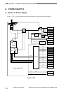
B. Power Supply Circuitry
1. AC Power Supply
AC power is supplied to the power supply PCB when the power plug is connected and the
front door switch (DS1) is turned on.
2. DC Power Supply
The power supply PCB provides three types of DC outputs: +24 V, +5 VR, and +5 VU.
When the power plug is connected and the front door switch (DS1) is turned on, the power
supply PCB supplies the DC controller PCB with +5 VR.
The copier uses a soft switch as its power switch so that it continues to supply the DC
controller PCB with +5 VR even when the power switch is off.
When the power switch is turned on, the CPU generates the DC power supply signal.
In response to the DC power supply signal, the power supply PCB generates +24 V and
+5VU. This condition turns on the AC power supply relay (RL) on the power supply PCB,
thereby making a switch-over to the fixing heater and the lamp regulator PCB.
When the power switch is turned off, the AC power supply relay (RL) on the power supply
PCB switches over to the options heater.
Reference:
The tolerance of DC voltage is as follows:
• +24 V ±5%
• +5 VU +5%, -7%
• +5 VR ±5%
However, the above applies only when the inaccuracy of the AC input is limited to ±10%.
Caution:
Be sure to disconnect the power plug whenever you have to replace the DC controller
PCB.