


CHAPTER 6 FIXING SYSTEM
6–6
COPYRIGHT
©
1998 CANON INC. CANON NP7161/NP7160 REV.0 AUG. 1998 PRINTED IN JAPAN (IMPRIME AU JAPON)
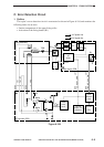
2. Surface Temperature of the Fixing Upper Roller
The main thermistor (TH1) and the sub thermistor are arranged nearby at the rear of the
fixing upper roller, and are used to monitor the difference in voltage between two thermistor
signals (TH1, TH2).
If either thermistor suffers an open circuit, the CW input terminal of the differential amplifier
circuit will be about 5 V. At this time, the voltage of the other thermistor will decrease as the
surface temperature of the fixing upper roller increases, gradually increasing the output of the
differential amplifier circuit.
When the output of the differential amplifier circuit exceeds the value set on the comparator,
the comparator will send a signal to the gate array. When the gate array detects the signal from
the comparator for a specific period of time, the DC controller PCB will cut off 24 V and AC
power supply and, at the same time, will indicate ‘E000’, ‘E002’, or ‘E003’.
If the connector of the main thermistor is not connected or both thermistors suffer an open
circuit, the microprocessor will not be able to detect any excess increases in the surface
temperature of the fixing upper roller, causing it to indicate ‘E000’, ‘E002’, or ‘E003’ on the
control panel.
3. Activation of the Fixing Heater (H1)
The fixing heater error signal (HEAT_ERR) from the AC drier is monitored by IC113 on the
DC controller PCB, and its reading is compared against the fixing heater drive signal
(HEAT_DR) to find out whether the power to the fixing heater is normal or not.
If the microprocessor on the DC controller PCB identifies the state of the fixing heater to be
faulty, it will cut the power supplied to the fixing heater and, at the same time, will indicate
‘E001’ on the control panel.