1-67
Cisco ONS 15454 Installation and Operations Guide
November 2001
Chapter 1 Hardware Installation
Installation Checklist
• Holdover Stability: 3.7 x10
-7
/day, including temperature (< 255 slips in first 24 hours)
• Reference: External BITS, line, internal
1.16.14 Power Specifications
• Input power: -48 VDC
• Power consumption: 55W (fan tray only); 650W (maximum draw w/cards)
• Power Requirements: -42 to -57 VDC
• Power terminals: #6 Lug
1.16.15 Environmental Specifications
• Operating Temperature: 0 to +55 degrees Celsius
• Operating Humidity: 5 - 95%, non-condensing
1.16.16 Dimensions
• Height: 18.5 inches (40.7 cm)
• Width: 19 or 23 inches (41.8 or 50.6 cm) with mounting ears attached
• Depth: 12 inches (26.4 cm) (5 inch projection from rack)
• Weight: 55 lbs. (empty)
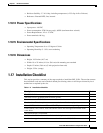
1.17 Installation Checklist
This section provides a summary of the steps required to install the ONS 15454. The section assumes
that individual cards are used with their default provisioning values or will be provisioned by local
technicians as required by the site.
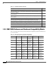
Table 1-11 Installation Checklist
Description Check
The ONS 15454 is mounted securely in the rack.
The ONS 15454 is grounded with the frame ground.
Power runs to the ONS 15454.
Visual and Audible alarm pins connect to central alarm collection equipment.
If used, BITS, LAN, Alarm, ACO, and CRAFT pins connect to corresponding cables.
If used, BITS, LAN, Alarm, ACO, and CRAFT cables are tiewrapped and routed under
screw holes.
The preferred EIAs are installed.
Coaxial and/or DS-1 cables are installed on the backplane.
Laced or tiewrapped coaxial cables run onto the sides of the ONS 15454.


