


1-33
Cisco ONS 15454 Installation and Operations Guide
November 2001
Chapter 1 Hardware Installation
Alarm, Timing, LAN, and Craft Pin Connections
Note The X.25, Modem, and TBOS pin fields are not active.
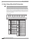
1.9.1 Alarm Installation
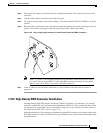
The alarm pin field supports up to 17 alarm contacts, including four audible alarms, four visual alarms,
one alarm cutoff (ACO), and four user-definable alarm input and output contacts.
Audible alarm contacts are in the LOCAL ALARM AUD pin field and visual contacts are in the LOCAL
ALARM VIS pin field. Both of these alarms are in the LOCAL ALARMS category. User-definable
contacts are in the ENVIR ALARM IN and ENVIR ALARM OUT pin fields. These alarms are in the
ENVIR ALARMS category; you must have the AIC card installed to use the ENVIR ALARMS. Alarm
contacts are Normally Open (N/O), meaning that the system closes the alarm contacts when the
corresponding alarm conditions are present. Each alarm contact consists of two wire-wrap pins on the
shelf assembly backplane. Visual and audible alarm contacts are classified as Critical, Major, Minor, and
Remote. Figure 1-24 shows alarm pin assignments.
Visual and audible alarms are typically wired to trigger an alarm light at a central alarm collection point
when the corresponding contacts are closed. You can use the Alarm Cutoff pins to activate a remote ACO
for audible alarms. You can also activate the ACO function by pressing the ACO button on the TCC+
card faceplate. The ACO function clears all audible alarm indications. After clearing the audible alarm
indication, the alarm is still present and viewable in the Alarms tab in CTC.
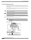
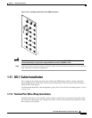
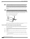
Procedure: Install Alarm Wires on the Backplane
Step 1 Use #22 or #24 AWG alarm wires.
Step 2 Wrap the alarm wires on the appropriate wire-wrap pins according to local site practice.
Note For information about attaching ferrites to wire-wrap pin fields, see the “Ferrite Installation”
section on page 1-61.
1.9.2 Timing Installation
The ONS 15454 backplane supports two Building Integrated Timing Supply (BITS) clock pin fields. The
first four BITS pins, rows 3 and 4, support output and input from the first external timing device. The
last four BITS pins, rows 1 and 2, perform the identical functions for the second external timing device.
Table 1-2 lists the pin assignments for the BITS timing pin fields.