


1-59
Cisco ONS 15454 Installation and Operations Guide
November 2001
Chapter 1 Hardware Installation
Cable Routing and Management
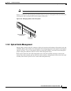
1.14.4 AMP Champ Cable Management
EIAs have cable management eyelets to tiewrap or lace cables to the cover panel. Tie wrap or lace the
AMP Champ cables according to local site practice and route the cables. If you configure the ONS 15454
for a 23-inch rack, two additional inches of cable management area is available on each side of the shelf
assembly. See the“AMP Champ EIA” section on page 1-20 and the “AMP Champ Connector
Installation” section on page 1-41 and the for more information.
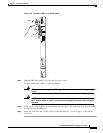
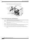
1.14.5 BIC Rear Cover Installation
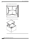
The ONS 15454 has an optional backplane interface connector (BIC) rear cover. This clear plastic cover
provides additional protection for the cables and connectors on the backplane (Figure 1-37). You can
also install the optional spacers if more space is needed between the cables and rear cover (Figure 1-38).
Figure 1-37 Clear BIC rear cover
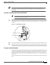
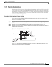
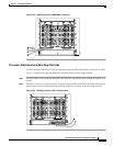
Procedure: Install the BIC Rear Cover
Step 1 Locate the three screws that run vertically along the edges of the backplane.
Only one pair of screws lines up with the screw slots on the mounting brackets, making them easy to
locate.
Step 2 Loosen the top and bottom screws on one edge of the backplane to provide room to slide the mounting
brackets into place using the u-shaped screw slots on each end.
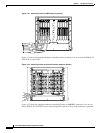
Step 3 Slide one of the mounting brackets into place and tighten the screws.
Step 4 Repeat Steps 2 and 3 for the second mounting bracket.
Step 5 Attach the cover by hanging it from the mounting screws on the back of the mounting brackets and
pulling it down until it fits snugly into place.
33916